Double mechanical seals use two sealing interfaces to create an additional controlled zone between the process and atmosphere. However, not all dual seals are arranged in the same physical direction. Tandem, back-to-back, and face-to-face configurations place the two seal sets differently, which changes how pressure, support fluid, leakage, heat, and transient conditions affect the assembly.
The most important point is that physical orientation and pressure strategy are not the same thing. A tandem seal is often associated with an unpressurized buffer system, while back-to-back designs are often associated with pressurized barrier fluid. Yet these are not universal rules. Seal manufacturers may use different geometries, and some face-to-face or tandem designs can operate in more than one pressure arrangement.
Therefore, engineers should select double mechanical seals from the complete drawing and operating philosophy, not from the arrangement name alone.
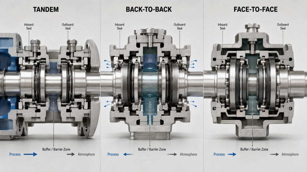
First Separate Seal Orientation from API Arrangement
Before comparing the three configurations, separate two questions. The first asks how the two seal sets are physically oriented. The second asks whether the fluid between them operates below or above seal-chamber pressure.
John Crane API 682 seal arrangements describe Arrangement 2 as a dual seal with the intermediate zone below seal-chamber pressure. This zone contains a clean buffer liquid or gas. Arrangement 3 instead keeps the intermediate zone above seal-chamber pressure and uses a barrier fluid.
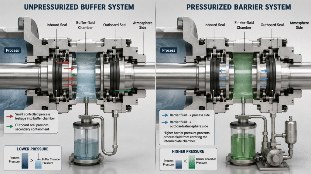
This pressure distinction controls leakage direction. In an unpressurized system, process fluid can leak across the inboard seal into the buffer zone. In a pressurized system, clean barrier fluid tends to leak toward the process and toward the atmosphere.
Do not automatically translate “tandem” into Arrangement 2 or “back-to-back” into Arrangement 3. Those combinations are common, but orientation alone does not define the API function. AESSEAL face-to-face seal designs include configurations intended for API 682 Category 2 and 3 applications. Always confirm the manufacturer’s cross-section and support plan.
Tandem Double Mechanical Seals: Two Seals in Series
In a tandem configuration, the two sealing stages sit in series and generally point in the same overall direction. Some manufacturers also describe this geometry as face-to-back. The inboard seal acts as the primary process seal, while the outboard seal provides secondary containment.
Tandem double mechanical seals often work with an unpressurized buffer fluid. The buffer pressure remains below the seal-chamber pressure. Small leakage from the primary seal therefore enters the buffer zone instead of flowing directly to atmosphere. The outboard seal then controls leakage from that intermediate zone.
This arrangement can be useful when the process must not be contaminated by an external barrier liquid. It also gives operators a controlled location where they can monitor primary-seal leakage.
What Happens if the Inboard Seal Starts Leaking?
When the primary seal wears, process fluid enters the buffer system. A rising reservoir level, pressure change, or other monitored condition can provide warning before leakage becomes uncontrolled.
However, the outboard seal should not become an excuse to ignore the primary failure. Process fluid may change the buffer’s lubricity, vapor pressure, or chemical compatibility. Hazardous products may also require a closed recovery or vapor-control system.
A tandem design works best when the maintenance team understands the expected leakage path and monitors the support system accordingly.
Back-to-Back Double Mechanical Seals: Strong Process Isolation
Back-to-back double mechanical seals place the two seal assemblies in opposing directions. In many traditional designs, the barrier-fluid region lies between them and operates at a higher pressure than the process seal chamber.
This pressure difference keeps the process away from the inboard sealing interface. Clean barrier fluid lubricates the faces and leaks in controlled small quantities across the inboard seal toward the process. The same barrier system also supports the outboard seal.
This approach is attractive for abrasive, crystallizing, polymerizing, toxic, or poorly lubricating liquids. Instead of asking the process fluid to lubricate the critical sealing faces, the seal uses a selected clean fluid.
Flowserve dual seal piping plans show this operating principle in pressurized Plans 53A, 53B, and 53C. Plan 54 can also supply a pressurized external barrier source. The exact system depends on pressure, heat load, utilities, and site requirements.
Why Barrier-Pressure Loss Matters
A pressurized double seal depends on maintaining the intended pressure differential. If barrier pressure falls below seal-chamber pressure, the leakage direction can reverse.
Process fluid may then enter the barrier cavity. That contamination can damage faces, attack elastomers, clog circulation paths, or create unsafe reactions with the barrier liquid. Depending on the seal design, pressure reversal can also disturb face loading.
Therefore, operators should monitor barrier pressure, level, temperature, and circulation. A back-to-back seal cannot deliver process isolation if the support system loses its pressure advantage.
Face-to-Face Double Mechanical Seals: Compact but Design-Specific
Face-to-face double mechanical seals orient the two sealing stages toward one another. This configuration can create a compact dual-seal package, especially in engineered cartridge designs where axial space, stationary components, and circulation paths are carefully integrated.
However, face-to-face should not be treated as a single pressure philosophy. Manufacturer designs show that the same general orientation may support pressurized or unpressurized service. AESSEAL face-to-face seal designs, for example, include configurations intended for API 682 Category 2 and 3 applications.
This is why a catalog photograph cannot tell you how the seal should be piped. The drawing must identify the inboard face pair, outboard face pair, barrier or buffer zone, pressure limits, rotation requirements, and circulation path.
Face-to-face geometry may also change how heat moves through the cartridge and how closely the two face sets interact thermally. Therefore, the support system and cooling strategy must match the complete seal design.
Tandem vs Back-to-Back vs Face-to-Face: Practical Comparison
| Factor | Tandem | Back-to-Back | Face-to-Face |
|---|---|---|---|
| General physical layout | Two stages in series, same general direction | Two seal stages opposed away from each other | Two seal stages oriented toward each other |
| Common pressure approach | Often unpressurized buffer | Often pressurized barrier | Can be pressurized or unpressurized |
| Primary purpose | Secondary containment and leakage monitoring | Process isolation with clean barrier fluid | Compact engineered dual sealing with design-specific pressure strategy |
| Typical leakage direction | Process → buffer zone → outboard seal | Barrier → process and barrier → atmosphere | Depends on pressure arrangement |
| Key support concern | Buffer contamination and outboard-seal condition | Loss of barrier pressure | Correct circulation, pressure logic, and manufacturer geometry |
| Selection warning | Do not assume all tandem seals are unpressurized | Pressure reversal can defeat isolation | Do not infer operation from appearance |
This table provides a starting point, not a universal design rule. Different manufacturers use different stationary or rotating architectures. Springs, balance diameters, pumping devices, and face directions can also vary.
For this reason, double mechanical seals should always be reviewed from the sectional drawing before installation or piping changes.
Buffer Fluid vs Barrier Fluid Changes the Failure Mode
The liquid between the two seal stages has a different job depending on pressure.
A buffer fluid operates below seal-chamber pressure. It provides lubrication and cooling for the outboard seal while accepting controlled leakage from the process side. API Plan 52 is a common support concept for a liquid-buffered Arrangement 2 seal.
A barrier fluid operates above seal-chamber pressure. It isolates the process from the sealing interface and supplies clean lubrication to the dual seal. Plans 53A, 53B, 53C, and 54 are common pressurized liquid-barrier concepts.
This difference matters more than the arrangement name. The support fluid must remain compatible with the process, seal materials, and product-quality requirements. If inward barrier leakage would contaminate food, pharmaceutical product, catalyst, or another sensitive stream, the fluid choice needs special review.
Our API 682 seal flush plans guide explains how process-side Plans 11, 21, and 23 control the environment around single seals. Dual systems add another zone and need a separate buffer or barrier strategy.
How to Choose the Correct Double Mechanical Seal Arrangement
Start with the consequence of leakage. If small process leakage can enter a monitored buffer system but must not reach atmosphere, a tandem-style unpressurized arrangement may be appropriate. If the process must be isolated from the seal faces, a pressurized dual arrangement may be more suitable.
Next, review process compatibility. Abrasive solids, crystallization, poor lubricity, polymerization, toxicity, volatility, and temperature can justify clean barrier lubrication. However, the barrier liquid must not react with or damage the process.
Pressure deserves special attention. Record normal seal-chamber pressure, maximum pressure, startup conditions, shutdown conditions, and possible reverse-pressure events. Do not select a seal only from pump discharge pressure.
Finally, check shaft size, axial space, gland dimensions, rotation, cooling needs, and available utilities. A cartridge mechanical seal range can simplify installation, but the cartridge still needs the correct orientation and support system.
If you are still deciding whether two seals are necessary at all, review our single vs double mechanical seals guide before comparing the three dual orientations.
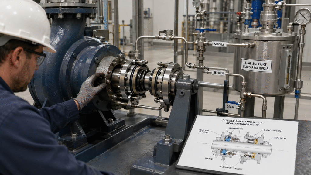
Common Selection and Maintenance Mistakes
One common mistake is copying a seal arrangement from another pump handling the same chemical. Different pumps may have different seal-chamber pressures, speeds, heat loads, and available space.
Another mistake is setting barrier pressure without considering transients. A system that has adequate differential pressure during normal operation may lose it during startup, shutdown, or process upsets.
Technicians should also avoid treating the support system as separate from the mechanical seal. Empty reservoirs, blocked lines, trapped air, poor cooling, contaminated fluid, and incorrect valve positions can damage both face pairs.
Material compatibility remains essential as well. A mechanical seal material selection guide should cover process fluid, buffer or barrier fluid, cleaning chemicals, temperature, and any contamination expected after an inboard-seal failure.
Finally, never identify tandem, back-to-back, or face-to-face geometry only from the outside appearance. When replacing double mechanical seals, request the sectional drawing, port identification, pressure requirement, face materials, elastomers, and support-plan information.
Frequently Asked Questions
Is a Tandem Seal Always Unpressurized?
No. Tandem geometry and pressure arrangement describe different aspects of the seal. Tandem designs commonly use an unpressurized buffer system, but engineered exceptions exist. Confirm the seal manufacturer’s drawing and operating instructions.
Is Back-to-Back Always an API Arrangement 3 Seal?
No. Back-to-back designs are strongly associated with pressurized barrier service, but the orientation name alone does not prove API Arrangement 3 compliance. Confirm barrier pressure, hardware, instrumentation, and the specified seal arrangement.
Which Arrangement Gives the Best Protection from Dirty Process Fluid?
A correctly designed pressurized dual seal can keep dirty or poorly lubricating process fluid away from the critical inboard face interface. However, reliability also depends on barrier-fluid compatibility, pressure control, circulation, materials, and solids management.
Can Face-to-Face Double Mechanical Seals Use Barrier Fluid?
Yes. Face-to-face designs can be engineered for pressurized service. Some manufacturer designs also support more than one API arrangement. Therefore, do not select the support plan from geometry alone.
Conclusion
Tandem, back-to-back, and face-to-face describe how two seal stages are physically arranged. They do not, by themselves, define the pressure strategy or API arrangement.
Tandem systems often emphasize containment with a lower-pressure buffer. Back-to-back systems often use higher-pressure barrier fluid for process isolation. Face-to-face systems can provide compact engineered solutions with pressure behavior defined by the specific design.
The safest way to select double mechanical seals is to evaluate leakage consequences, process chemistry, pressure differential, support fluid, heat removal, available space, materials, and transient conditions together. Then confirm the final choice against the manufacturer’s sectional drawing and support-system requirements.