API 682 seal flush plans help control the environment around mechanical seal faces. Plan 11, Plan 21, and Plan 23 all use process liquid to support a single seal, but they move and cool that liquid in different ways. Choosing the wrong plan can leave the seal too hot, reduce vapor margin, increase coking, or create unnecessary cooler load.
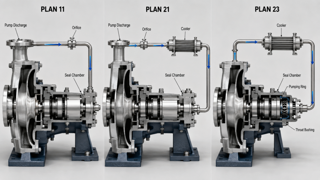
The phrase “seal flush plan” is widely used in industry. More precisely, API 682 defines piping plans for seal support. Plan 11 and Plan 21 bring process liquid from a higher-pressure part of the pump into the seal chamber. Plan 23 instead circulates liquid from the seal chamber through a cooler and back again.
That difference becomes important in hot-water, hydrocarbon, and other temperature-sensitive services.
What API 682 Seal Flush Plans Are Designed to Do
API Standard 682 covers shaft sealing systems for centrifugal and rotary pumps used mainly in petroleum, natural gas, and chemical service. A piping plan does not replace the mechanical seal. Instead, it creates operating conditions that help the seal faces remain lubricated, cooled, and stable.
For a conventional wet-running seal, the liquid around the faces must remain in a suitable phase. If temperature approaches the liquid’s boiling point at seal-chamber pressure, vapor formation can disturb the lubricating film. Our article on what happens when a mechanical seal runs dry explains why loss of a stable liquid film can quickly increase friction and heat.
Flowserve mechanical seal piping plans describe Plan 11, Plan 21, and Plan 23 as process-side arrangements for single seals. EagleBurgmann API piping plans use the same basic distinction: pressure-driven circulation for Plan 11, cooled pressure-driven circulation for Plan 21, and a local forced cooling loop for Plan 23.
Therefore, the question is not simply, “Does the seal need cooling?” Engineers must decide where circulation should come from, how much heat must be removed, and how much hot process liquid should enter the seal chamber.
Plan 11: Basic Discharge Recirculation
API Plan 11 takes process fluid from pump discharge, passes it through a flow-control orifice, and sends it into the seal chamber. The pressure difference between pump discharge and the seal chamber drives the flow.
Among common seal flush plans, Plan 11 is one of the simplest arrangements for clean, non-polymerizing liquids. It needs no cooler and relatively little external equipment.The incoming flush removes heat from the seal chamber, helps vent horizontal pumps, and can increase seal-chamber pressure and vapor margin.
Where Plan 11 Works Well
Plan 11 is a strong starting point when the pumped liquid is clean, stable, and not excessively hot. The piping is simple, inspection is straightforward, and there is no heat exchanger to maintain.
However, the orifice must provide adequate flow. A blocked orifice can remove the cooling and circulation that the seal depends on. Therefore, maintenance teams should monitor the flush line and investigate abnormal temperature differences.
Plan 11 also does not cool the discharge liquid before it reaches the seal. If the process fluid is already hot, sending more hot liquid into the chamber may not provide enough vapor margin. Plan 21 or Plan 23 may then provide better temperature control.
Plan 21: Plan 11 with a Cooler
API Plan 21 follows the same basic path as Plan 11 but adds a cooler between the discharge connection and seal chamber. Process liquid leaves a high-pressure region, passes through the flow-control orifice and cooler, and enters the seal chamber at a lower temperature.
The cooler improves heat removal. Lower fluid temperature increases the margin between seal-chamber conditions and vaporization. In addition, it can reduce the risk of coking in suitable hot hydrocarbon applications.
Engineers often select Plan 21 for clean higher-temperature liquids and hot-water service. It is especially useful when the basic Plan 11 circulation concept is suitable, but the discharge fluid reaches the seal chamber at an undesirable temperature.
The Main Limitation of Plan 21
The cooler continuously receives hot process liquid from a high-pressure area of the pump. Consequently, it may need to remove both seal-generated heat and substantial process heat carried into the flush stream.
This can create a higher cooler duty than a properly designed Plan 23. Cooling-water demand, heat-exchanger fouling, venting, and pressure drop also become important maintenance considerations.
Therefore, Plan 21 is not automatically an upgrade for every Plan 11 application. Use it when additional cooling is required and the continuous cooled discharge flush remains practical for the process.
Plan 23: A Local Closed Cooling Loop
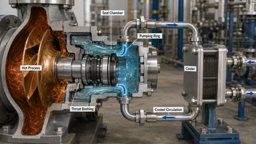
API Plan 23 uses a different circulation concept. Instead of continuously taking fresh hot liquid from pump discharge, an internal pumping device circulates liquid from the seal chamber through a cooler and back into the chamber.
A close-clearance throat bushing helps restrict mixing between the cooler seal-chamber liquid and hotter process fluid inside the pump. Therefore, the cooling loop concentrates on controlling the local environment around the mechanical seal.
This design explains why Plan 23 can provide efficient seal cooling with relatively low cooler duty. It is widely associated with hot water, boiler feed water, hot hydrocarbons, and other clean high-temperature services where maintaining adequate vapor margin is important.
Why the Pumping Ring Matters
Plan 23 normally depends on an internal circulation device, commonly called a pumping ring. The mechanical seal and external piping must therefore operate as one hydraulic loop.
Excessive piping resistance can reduce circulation. Likewise, trapped air can interfere with effective liquid movement and heat transfer. High points must be vented correctly, while cooler and piping arrangements should follow the approved seal-system design.
Correct commissioning is especially important. A mechanical seal installation guide should be used together with the supplier’s Plan 23 drawing and pump-specific instructions.
Plan 11 vs Plan 21 vs Plan 23: Quick Comparison
| Feature | Plan 11 | Plan 21 | Plan 23 |
|---|---|---|---|
| Circulation source | Pump discharge pressure | Pump discharge pressure | Internal pumping device |
| Cooler | No | Yes | Yes |
| Main flow path | Discharge → orifice → seal chamber | Discharge → orifice → cooler → seal chamber | Seal chamber → pumping device → cooler → seal chamber |
| Typical starting service | Clean, moderate-temperature liquid | Clean, hotter liquid | Hot water and high-temperature clean service |
| Heat removal | Basic | Improved | Efficient local cooling |
| Cooler duty | None | Can be relatively high | Usually lower than Plan 21 |
| Throat bushing importance | Application dependent | Application dependent | Important for limiting hot process mixing |
| Typical maintenance concern | Plugged orifice | Orifice or cooler fouling | Poor circulation, air, or cooler fouling |
This comparison of seal flush plans is a selection overview rather than an engineering specification. Actual flow rate, orifice size, cooler duty, pipe diameter, throat-bushing clearance, and instrumentation must match the real pump and operating conditions.
How to Choose Between These Seal Flush Plans
Start with process temperature and vapor margin. If the liquid is clean and remains safely liquid inside the seal chamber, Plan 11 may provide adequate circulation. Its simplicity becomes a reliability advantage when additional cooling is unnecessary.
If Plan 11 provides the correct circulation concept but discharge temperature is too high, Plan 21 adds cooling without changing the fundamental source of flush flow. It can therefore provide a practical intermediate solution.
Choose Plan 23 when stronger local temperature control is required and continuously cooling fresh discharge liquid would create unnecessary cooler duty. This is particularly relevant to hot water and boiler feed applications.
Do Not Select by Temperature Alone
Fluid cleanliness matters. Plans 11, 21, and 23 are generally applied to clean, non-polymerizing fluids. Solids can plug an orifice, foul a cooler, damage seal faces, or interfere with Plan 23 circulation.
Seal arrangement also matters. This comparison focuses on process-side support for conventional single seals. If the fluid requires additional containment or isolation, review single vs double mechanical seals before deciding that a single-seal recirculation system is sufficient.
Finally, check pressure, vapor pressure, viscosity, shaft speed, face materials, available cooling water, startup conditions, and seal-chamber geometry. Piping-plan selection must match the complete operating system.
Common Mistakes with Plans 11, 21 and 23
The first mistake is treating Plan 21 as automatically better than Plan 11. A cooler adds heat-removal capability, but it also adds equipment, pressure loss, venting requirements, and maintenance. If Plan 11 already provides a stable environment, this additional complexity may offer little benefit.
The second mistake is assuming Plan 23 is simply a better-cooled Plan 21. Their hydraulic concepts differ. Plan 21 brings liquid from pump discharge. Plan 23 repeatedly circulates the local seal-chamber liquid through a pumping device and cooler.
The third mistake is ignoring startup conditions. A cooler loop containing trapped air cannot perform as intended. A closed valve, blocked orifice, fouled exchanger, or incorrectly connected pipe can also remove cooling. These conditions may eventually contribute to thermal assault in mechanical seals.
Finally, do not copy a piping plan from another pump without reviewing its operating data. Pumps handling the same liquid can still have different pressure, speed, chamber geometry, heat generation, and available connections.
What Maintenance Teams Should Monitor
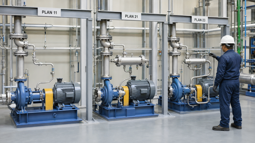
For Plan 11, confirm that the flush line remains open and the orifice is not clogged. Temperature checks can help identify lost circulation. Also inspect the chamber and piping for deposits.
For Plan 21, include cooler performance in the maintenance routine. Monitor inlet and outlet temperatures, cooling-water condition, fouling, and blocked flow. Remove trapped air from high points before operation.
For Plan 23, vent the circulation loop completely and verify that the pumping device generates adequate circulation. Inspect the throat bushing and cooler. When the process requires it, engineers can also add equipment such as a magnetic separator.
A mechanical seal leaking after installation can result from an incorrect support-system setup as well as a damaged seal. Therefore, troubleshooting should include valve positions, flow paths, pressure, temperatures, and piping connections before replacing the mechanical seal.
Frequently Asked Questions
Is Plan 21 Always Better Than Plan 11?
No. Plan 21 provides additional temperature control, but Plan 11 is simpler. For clean, moderate-temperature service with adequate vapor margin, Plan 11 may provide the more economical and maintainable solution.
Why Is Plan 23 Often Preferred for Hot Water?
Plan 23 recirculates and cools liquid around the seal chamber instead of continuously cooling fresh discharge liquid. With effective circulation and a suitable throat bushing, it can maintain a cooler local environment with relatively low cooler duty.
Does Plan 23 Need an External Pump?
Normally, circulation is generated by a pumping device associated with the mechanical seal. The exact design depends on the seal manufacturer. The loop must provide sufficient circulation while keeping piping resistance under control.
Can Plan 11, 21 or 23 Handle Dirty Slurry?
They are not universal slurry solutions. Solids can plug orifices, foul heat exchangers, and damage sealing surfaces. Dirty service may require solids separation, an external clean flush, another API piping plan, or a different seal arrangement.
Conclusion
API 682 seal flush plans Plan 11, Plan 21, and Plan 23 solve related problems in different ways. Plan 11 uses simple discharge recirculation. Plan 21 cools that discharge flush before it reaches the seal. Plan 23 creates a cooled local circulation loop around the seal chamber.
For clean moderate-temperature service, Plan 11 often provides the simplest solution. Plan 21 is useful when discharge flush requires cooling. Plan 23 becomes attractive when hot service demands efficient local temperature control and stronger vapor margin.
The final selection should always consider fluid properties, temperature, pressure, vapor margin, seal design, pump geometry, cooler performance, and the site’s ability to maintain the support system.