Shaft runout and misalignment often hide behind a familiar maintenance story: the seal is replaced, the pump restarts, and the same leak returns. The new seal becomes the suspect because it is the visible failure point. Yet the faces may only be recording motion that begins in the shaft, bearings, coupling, baseplate, or piping.
Treat the failed seal like evidence rather than a disposable part. This guide follows the motion backward from the wear track to the machine. It shows what shaft runout and misalignment actually change at the sealing interface, which clues matter during teardown, and what technicians should measure before another seal goes into the pump.
Start With the Evidence, Not the Spare Seal
A mechanical seal works best when the rotating face stays square and stable against the stationary face. The faces still need a microscopic liquid film, but that film assumes controlled motion. Therefore, every unwanted radial or angular movement changes the contact condition that the seal must track.
A bent shaft, worn bearing, distorted gland, pipe strain, or poor coupling alignment can all disturb that relationship. As a result, the seal may leak only while the shaft rotates. It may look dry at rest because the faces can close normally when dynamic movement disappears.
Separate Runout From Misalignment Before Diagnosing
Shaft runout describes how far a rotating shaft or sleeve moves away from its ideal centerline as it turns. Misalignment usually describes shafts or machine components whose centerlines do not share the intended position. They can occur together, but they are not interchangeable terms.
For example, a straight shaft can still operate with poor pump-to-motor alignment. Likewise, a well-aligned coupling cannot correct a bent shaft near the seal chamber. Therefore, shaft runout and misalignment require separate measurements before technicians decide what to repair in the machine.
One Revolution at a Time: What Shaft Runout Does
Imagine the rotating face making one revolution while its center moves slightly from side to side. The stationary face must follow that motion while maintaining a stable fluid film. At low movement, the seal may tolerate the disturbance. However, excessive runout produces repeated changes in face contact, film thickness, and spring movement.
Those changes happen once during every shaft revolution. Consequently, even a small geometric error becomes a high-frequency mechanical input at normal pump speed. The seal head may move axially, the secondary seal may slide more than intended, and the contact band can become wider or uneven.
Repetition Turns Small Motion Into Wear
Repeated face movement can disturb lubrication and create local heat. In addition, the rotating assembly may transmit cyclic loads into springs, bellows, drive pins, and O-rings. A pusher seal can show fretting or hang-up if its dynamic secondary seal must constantly compensate.
John Crane machine tolerance checks include shaft runout, end play, chamber concentricity, and chamber-face squareness before cartridge installation. Those checks matter because the seal is designed around a controlled rotating axis. Therefore, the pump condition should meet the specific seal and machine requirements before startup.
Misalignment Starts at the Coupling but Does Not Stay There
Coupling misalignment changes more than the relationship between two coupling hubs. It can raise bearing loads, increase vibration, distort shaft motion, and transmit forces into the pump casing. Therefore, a seal may experience the result indirectly even when the misalignment exists several centimeters away.
Two basic forms are common. Offset misalignment leaves the shaft centerlines roughly parallel but displaced. Angular misalignment makes the centerlines meet at an angle. In practice, many pump trains contain some combination of both, especially after base movement, piping work, or motor replacement.
Why a Flexible Coupling Does Not Protect the Seal
A flexible coupling can tolerate limited misalignment without immediately breaking. However, tolerance does not mean the connected machine operates without added forces. Bearings and shafts still react to the geometry, and the seal sees the resulting dynamic movement during every operating cycle.
SKF shaft alignment guidance lists increased vibration, premature bearing wear, coupling wear, and accelerated deterioration of mechanical seals among the effects of poor alignment. Therefore, technicians should align the pump and driver to the equipment criteria rather than treating coupling flexibility as permission for poor setup.
Read the Wear Track Before You Clean the Parts
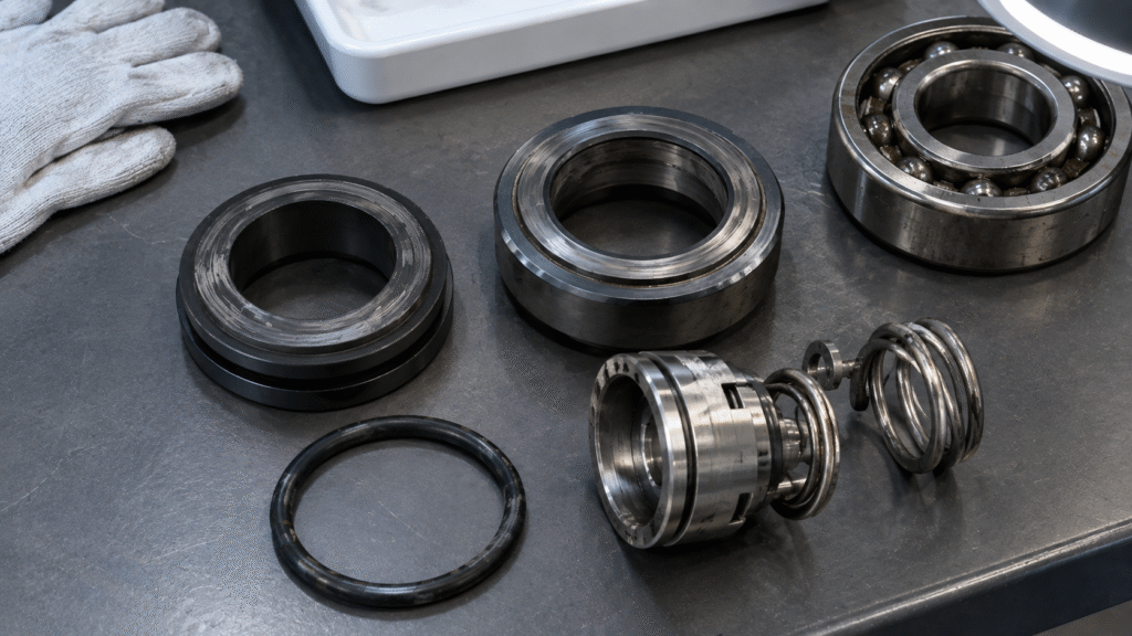
A damaged seal face is evidence. Before cleaning or polishing anything, photograph the rotating and stationary faces under even light. Also record which side faced the process, the position of the drive features, and whether the pump leaked while stopped or only while running.
A wide contact track may suggest that the faces are moving relative to each other. An eccentric or interrupted track can point toward concentricity, squareness, or shaft-motion problems. However, deposits and dry running can create other patterns, so one visual clue should never stand alone.
Symptoms That Point Back to the Machine
Repeated failures deserve special attention when the replacement seal uses the correct materials and dimensions. Leakage that changes with speed, abnormal bearing noise, increased vibration, and uneven face wear all strengthen the case for checking shaft runout and misalignment first.
If a mechanical seal is leaking after installation, compare the leak timing with the pump condition. A seal that stays dry while stationary but leaks during rotation can indicate runout, misalignment, bearing wear, shaft deflection, or gland problems. This is why shaft runout and misalignment belong in a repeat-failure check. Therefore, replacing faces before measuring motion may simply reset the failure clock.
Measure Before You Replace
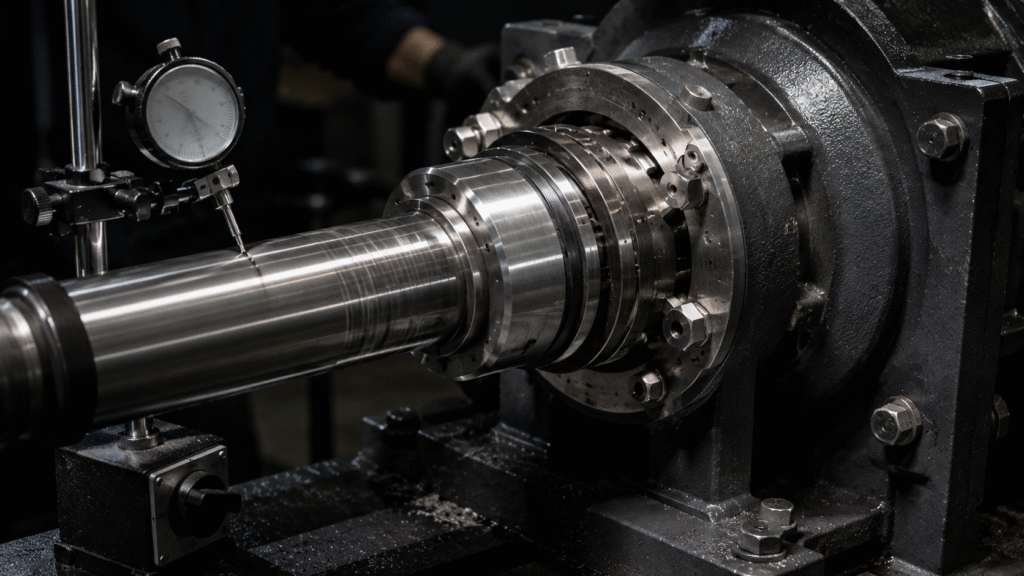
Start with the shaft or sleeve near the seal location because shaft runout and misalignment need measured evidence. Mount a dial indicator on a stable reference and rotate the shaft slowly by hand. The reading shows total indicated movement at that point. However, the acceptable value must come from the pump or seal manufacturer because equipment designs and speeds differ.
Next, check axial movement and the relationship between the shaft and seal chamber. Also verify gland-face squareness and chamber concentricity when the seal design requires those checks. The general mechanical seal installation guide can help organize these machine-condition checks before assembly.
Alignment Needs Its Own Measurement
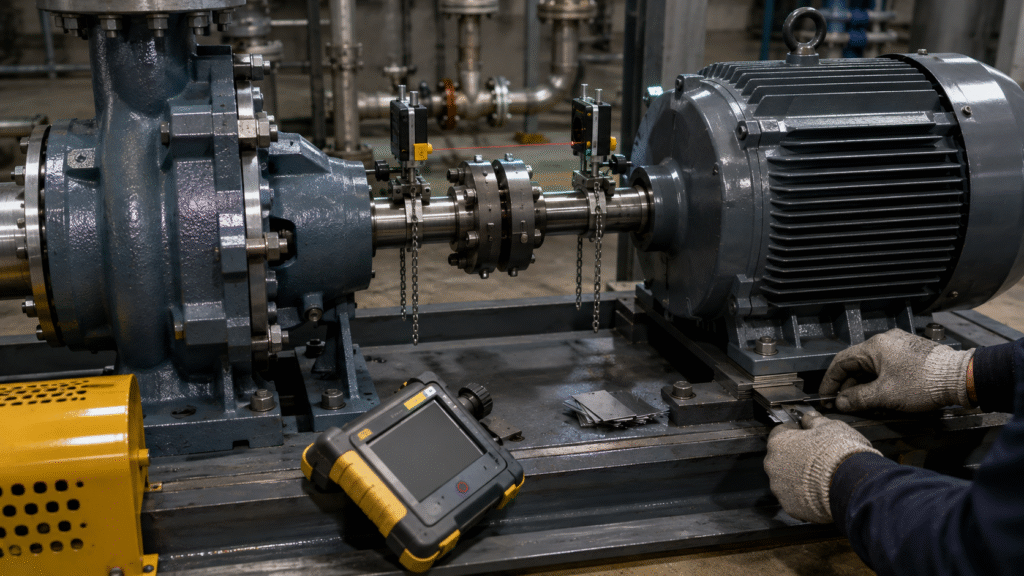
Coupling alignment requires measurements in both vertical and horizontal planes. Depending on the equipment, technicians may use dial indicators or a laser alignment system. First correct obvious soft foot, loose hold-down hardware, or damaged shims. Then align the driver and pump according to the machine instructions.
Finally, recheck alignment after piping is connected and after all hold-down bolts are secure. Pipe strain can move a pump that was correctly aligned earlier. For temperature-sensitive machines, the required cold alignment may also account for thermal growth during operation.
Trace Shaft Motion Backward Through the Pump
Runout does not automatically mean the shaft itself is bent. A damaged sleeve, debris under a sleeve, worn bearing, loose fit, or incorrect assembly can also create an eccentric reading. Therefore, move the dial indicator to several locations when practical and compare the pattern.
Misalignment has a similar chain of causes. Soft foot, baseplate distortion, poor grouting, loose anchors, coupling errors, pipe strain, and thermal movement can shift the machine. In addition, bearing wear can create movement that looks like an alignment problem during operation.
Pipe Strain Can Undo a Good Alignment
A pump may align correctly before technicians connect the suction and discharge piping. Then the piping pulls the casing into a new position when flange bolts are tightened. As a result, coupling alignment changes and internal clearances can shift after the piping work.
Do not use flange bolts to pull poorly fitted pipe into place. Instead, support and fit the piping so it meets the pump naturally. After piping work, verify alignment again. This simple sequence prevents the seal from becoming the first component that reveals a piping problem.
The Damage Chain From Shaft Motion to Leakage
Mechanical seals need a stable fluid film. Excessive motion changes the film thickness and can force parts of the faces into heavier contact. Consequently, local friction rises while other areas may momentarily separate. The result can include heat checking, accelerated carbon wear, chipped hard faces, or visible leakage.
Secondary seals also suffer. O-rings may slide or flex more often, bellows may cycle farther, and drive components may see repeated side loading. In addition, shaft or sleeve fretting can develop where a dynamic secondary seal repeatedly moves over the same surface.
Harder Faces Are Not a Mechanical Repair
It is tempting to respond to rapid wear by changing carbon to silicon carbide or tungsten carbide. Harder faces can improve abrasion resistance, but they cannot straighten a shaft or align a motor. Therefore, a mechanical seal material selection guide should support the fluid and wear requirements after the machine problem is understood.
Likewise, a more expensive cartridge cannot cancel excessive movement unless it was specifically engineered for that duty. Some special seals tolerate greater motion, but that is a design decision. It should not become an excuse to ignore repairable pump defects.
A Repeat-Failure Investigation Sequence
Do not begin with the spare seal. First, preserve the failed parts and record the leak history. Next, inspect bearings, shaft condition, sleeve fit, coupling, foundation, hold-down bolts, and piping. Then measure runout, axial movement, chamber geometry, and coupling alignment as required.
After correcting shaft runout and misalignment at their source, inspect the seal chamber and support system. Confirm that flushing, venting, pressure, and operating point are also suitable. Finally, use a guide to identify the correct mechanical seal if any doubt remains about dimensions, materials, or arrangement.
Restart With Evidence, Not Assumptions
Turn the shaft by hand when the equipment procedure allows it. Confirm free movement before coupling guards return to position. Next, prime and vent the pump, establish the required seal support flow, and start under controlled conditions with normal site precautions.
During the first run, monitor leakage, vibration, bearing behavior, pressure, and temperature. Compare those observations with the pre-repair condition and the original shaft runout and misalignment symptoms. Therefore, the restart becomes a verification step instead of a simple attempt to see whether the new seal survives.
What to Record for the Next Failure Analysis
A useful maintenance record needs more than the seal model. Record shaft runout readings, axial movement, coupling alignment results, bearing condition, and whether piping changed during the repair. In addition, photograph the face tracks before cleaning them and note whether leakage depended on speed or temperature.
Also record the pumped fluid, pressure, temperature, operating point, and support-system condition. These details help separate machine motion from dry running, chemical attack, or poor material selection. If symptoms change with suction conditions or flow, the separate guide on pump cavitation and vibration can help test a hydraulic cause. A mechanical seal installation and maintenance guide can provide a consistent framework for future inspections.
Fix the Axis Before You Blame the Seal
Shaft runout and misalignment shorten seal life because they make precision faces follow motion they were never meant to absorb continuously. The visible leak may appear at the seal, but the root cause can sit in the shaft, bearings, coupling, baseplate, or piping.
Therefore, repeated seal replacement should trigger measurement, not guesswork. Preserve the wear pattern, inspect the machine, measure the rotating geometry, verify alignment, and correct the source of motion. Once the pump runs on a stable axis, the mechanical seal has a much better chance to do its actual job.