A mechanical seal leaking after installation usually indicates an installation error, damaged sealing surface, incorrect seal setting, unsuitable mater
| identify the correct replacement mechanical seal |
ials, or a problem with the pump’s operating conditions.
Even a new, high-quality mechanical seal can leak immediately if technicians touch the seal faces, damage an O-ring, install the stationary seat unevenly, set the wrong working length, or start the pump without enough liquid in the seal chamber.
Therefore, replacing the seal again without identifying the real cause may only lead to another failure.
This guide explains the most common causes of mechanical seal leakage after installation, how to locate the leak, and what you should check before restarting the pump.
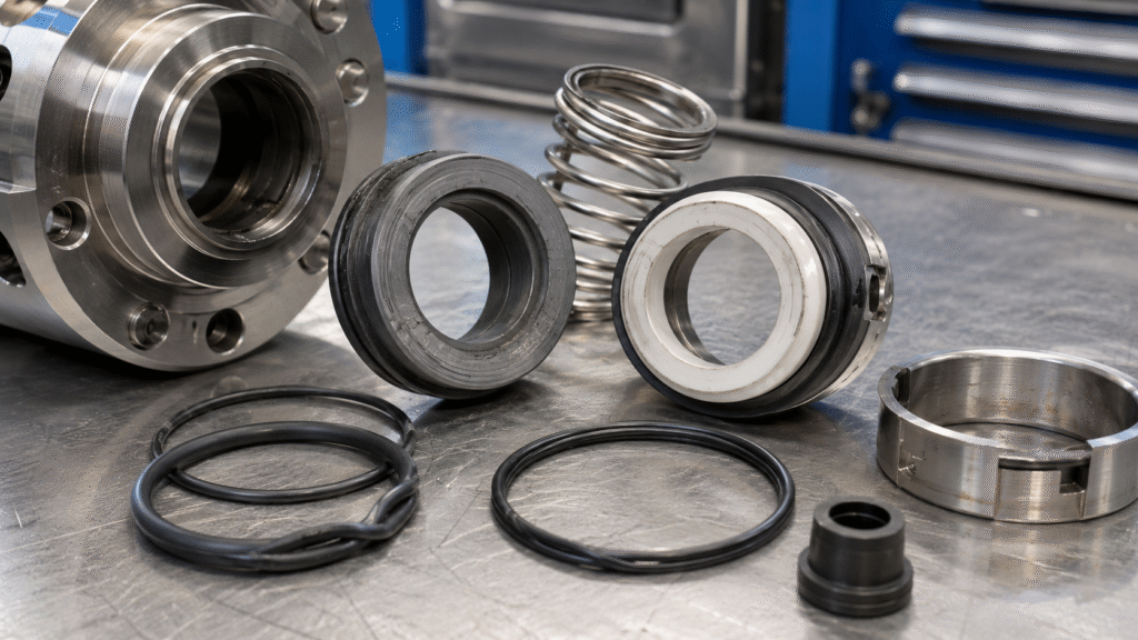
Quick Answer: Why Is a New Mechanical Seal Leaking?
A new mechanical seal may leak after installation because of:
- Dirty or damaged seal faces
- Cut, twisted, or incorrectly installed O-rings
- An unsuitable assembly lubricant
- Incorrect spring compression or working length
- Uneven stationary seat or gland installation
- Excessive shaft runout or pump misalignment
- Dry running or trapped air
- Incorrect seal face or elastomer materials
- Pressure, temperature, or speed outside the seal limits
- Blocked or incorrectly connected flush lines
- Excessive vibration or cavitation
- Incorrect mechanical seal size or design
First, determine exactly where the liquid comes from. Then check whether the seal leaks while the pump is stationary, during startup, only while running, or after the pump becomes hot.
The timing and location of the leakage often reveal the underlying problem.
Is a Small Amount of Mechanical Seal Leakage Normal?
A mechanical seal requires a very thin fluid film between its rotating and stationary faces. This film lubricates and cools the faces during operation.
However, in most liquid-pump applications, a correctly selected and installed mechanical seal should not produce continuous visible dripping.
A small amount of moisture, vapor, or temporary wetting may occur during initial operation. Nevertheless, continuous dripping, spraying, or a steadily increasing leak requires investigation.
Do not assume that a new seal simply needs more time to “wear in.” If leakage remains visible or increases, stop the pump and inspect the installation before the seal faces suffer further damage.
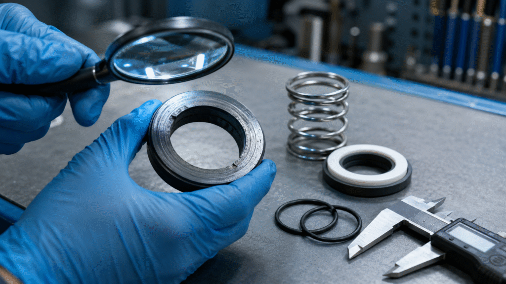
Identify When the Mechanical Seal Starts Leaking
Before disassembling the pump, observe when the leak appears.
| Leakage Pattern | Possible Causes |
|---|---|
| Leaks while the pump is stopped | Damaged O-ring, gland gasket, stationary seat, or incorrect static sealing |
| Leaks immediately at startup | Dry running, damaged faces, incorrect installation length, or wrong rotation |
| Leaks only while the shaft rotates | Shaft runout, vibration, misalignment, pressure, or face instability |
| Leaks after the pump becomes hot | Thermal distortion, incompatible materials, or insufficient cooling |
| Leaks intermittently | Cavitation, air entry, pressure fluctuation, or unstable operation |
| Leakage increases gradually | Face wear, solids accumulation, loss of lubrication, or chemical attack |
| Leakage appears after shutdown | Pressure reversal, trapped process liquid, or temperature-related movement |
This initial observation can prevent unnecessary disassembly and help you focus on the most likely failure area.
Where Can a Mechanical Seal Leak?
Not every leak near the seal comes through the primary sealing faces.
Liquid may escape through several paths:
- Between the rotating and stationary seal faces
- Between the stationary seat and seal housing
- Between the rotating element and pump shaft
- Around an O-ring, rubber cup, bellows, or gasket
- Between the gland and pump casing
- Through a flush, quench, cooling, or barrier-fluid connection
- From a damaged shaft sleeve or seal chamber
Therefore, clean and dry the area before testing. Then observe the first point where moisture appears.
This step is more reliable than assuming that every leak comes from the seal-face interface.
12 Common Causes of a Mechanical Seal Leaking After Installation
1. Dirty or Contaminated Seal Faces
Mechanical seal faces require extremely clean and flat contact surfaces.
Dust, fingerprints, grease, metal particles, lint, dried chemicals, or packaging debris can create a leakage path between the faces.
Even a small particle may hold the faces apart. As a result, the new mechanical seal may begin leaking as soon as the pump starts.
What to check
Inspect the seal faces under good lighting. Look for:
- Fingerprints
- Oil marks
- Dust or fibers
- Dried deposits
- Scratches
- Uneven contact marks
- Embedded particles
How to correct it
Clean the faces with a suitable residue-free cleaner and a lint-free cloth. Follow the seal manufacturer’s cleaning instructions.
Do not use abrasive paper or polishing compounds unless the manufacturer specifically recommends them. Abrasive cleaning can change the flatness of the seal face and permanently damage it.
During reassembly, avoid touching the lapped faces with bare fingers.
2. Chipped, Cracked, or Scratched Seal Faces
Carbon, ceramic, silicon carbide, and tungsten carbide faces can suffer damage during transportation or installation.
Carbon and ceramic components are especially vulnerable to impact. A minor chip near the sealing track can create immediate leakage.
Damage may occur when technicians:
- Drop the seal
- Strike it against the shaft
- Force it over a keyway
- Tighten components unevenly
- Use metal tools directly on the seal face
- Install the seat at an angle
What to check
Remove the seal and inspect the full circumference of both faces.
Look for:
- Edge chips
- Radial cracks
- Deep scratches
- Broken carbon sections
- Uneven wear tracks
- Heat discoloration
How to correct it
Replace damaged seal faces as a matched set.
Do not combine a new rotating face with a used stationary face unless the seal manufacturer specifically permits it. The old face may have an uneven wear pattern that prevents proper contact with the new component.
3. Damaged, Twisted, or Incorrectly Installed O-Rings
Secondary seals prevent leakage around the shaft, sleeve, stationary seat, and gland.
An O-ring may leak if installers cut, twist, pinch, stretch, roll, or install it in the wrong groove.
Sharp shaft shoulders, threads, keyways, burrs, or damaged sleeve surfaces frequently cut elastomers during assembly.
Typical signs
- Leakage while the pump is stationary
- Liquid appearing behind the rotating seal
- Leakage around the stationary seat
- A visibly twisted or extruded O-ring
- Rubber particles near the installation area
How to correct it
Remove burrs and protect sharp edges before installing the new O-ring.
Use an installation sleeve or protective tape over threads and keyways when appropriate. In addition, verify the O-ring size, material, groove position, and compression.
Never reuse an O-ring that shows cuts, flattening, swelling, hardening, or permanent deformation.
4. Incorrect Lubricant During Assembly
The wrong lubricant can damage elastomers or prevent the mechanical seal from remaining in its correct position.
For example, petroleum-based grease may attack some rubber materials. Excess lubricant can also contaminate the primary seal faces.
In addition, a lubricant that remains slippery after installation may allow a rubber bellows or rotating component to move along the shaft.
What to check
Confirm:
- Which lubricant the seal manufacturer recommends
- Whether the lubricant is compatible with the elastomer
- Whether lubricant contacted the sealing faces
- Whether the rotating element moved after installation
How to correct it
Use only a clean, compatible lubricant approved for the seal and process fluid.
Apply a small amount to the required secondary sealing surfaces. Do not coat the primary seal faces unless the manufacturer’s instructions specifically require it.
5. Incorrect Working Length or Spring Compression
The mechanical seal working length controls spring compression and face loading.
If the installed length is too long, the spring may not provide enough closing force. Consequently, liquid can pass between the faces.
If the installed length is too short, excessive spring compression may create high friction, rapid heat generation, face distortion, and premature wear.
Common causes
- Incorrect measurement
- Wrong shaft reference point
- Incorrect seat thickness
- Wrong replacement seal model
- Improper positioning of the drive collar
- Setting clips removed at the wrong stage
- Failure to follow the pump drawing
For cartridge mechanical seals, setting clips or spacers normally maintain the correct position during installation. Removing them too early can change the seal setting.
How to correct it
Check the specified installation dimension and compare it with the actual pump assembly.
Measure from the correct reference surface. Also verify the stationary seat thickness, shaft shoulder position, sleeve length, and gland location.
Do not estimate spring compression by appearance.
6. Uneven Stationary Seat or Gland Installation
The stationary seat must sit squarely in the seal housing.
If installers press one side deeper than the other, the stationary face may not remain perpendicular to the shaft. Uneven gland tightening can create the same problem.
As a result, the rotating face may contact only part of the stationary face.
What to check
Inspect:
- Stationary seat depth
- Seat squareness
- Rubber cup position
- Gland gasket alignment
- Bolt-tightening pattern
- Gland gap around the circumference
How to correct it
Clean the seat bore and remove corrosion or deposits.
Press the stationary seat evenly with a clean installation tool that applies force to the correct surface. Then tighten gland bolts gradually in a cross pattern.
Do not pull an angled gland into position by tightening one bolt completely.
7. Excessive Shaft Runout, Misalignment, or Bearing Wear
A new seal cannot correct a mechanical problem in the pump.
A bent shaft, worn bearing, damaged sleeve, loose coupling, or incorrect alignment can move the rotating face away from the stationary face during operation.
This explains why some seals remain dry while the pump is stopped but leak as soon as the shaft rotates.
Typical signs
- Leakage only during operation
- Uneven seal-face wear
- A wide or interrupted contact track
- Abnormal bearing noise
- High vibration
- Repeated seal failure
- Leakage that changes with pump speed
How to correct it
Measure shaft runout, axial movement, and coupling alignment with suitable instruments.
Inspect the bearings, shaft, sleeve, coupling, and pump mounting. Correct the mechanical condition before installing another seal.
Otherwise, the replacement seal may fail in the same way.
8. Dry Running or Trapped Air
Mechanical seal faces depend on the process liquid or a separate support fluid for lubrication and cooling.
If the pump starts with an empty seal chamber, the faces can generate damaging heat within a short time.
Trapped air can create a similar problem because air removes heat less effectively than liquid.
Common causes
- The pump was not primed
- The seal chamber was not vented
- The suction valve remained closed
- The liquid level was too low
- A flush line was closed or blocked
- The pump lost suction
- Air entered the inlet piping
Typical signs
- High-pitched noise during startup
- Rapid temperature increase
- Cracked or blistered carbon
- Heat marks on metal parts
- Polished or discolored seal faces
- Leakage that begins shortly after startup
How to correct it
Fill and vent the pump and seal chamber before startup.
Confirm that the suction system supplies liquid continuously. In addition, verify the flush or barrier-fluid flow before starting the main pump.
If the seal faces have already suffered thermal damage, replace them before restarting.
9. Incorrect Seal Face or Elastomer Materials
A mechanically correct installation may still leak when the materials do not match the pumped liquid.
Chemical incompatibility can cause elastomers to swell, soften, shrink, crack, or harden. Likewise, unsuitable face materials may corrode, blister, wear, or suffer thermal damage.
A reliable mechanical seal material selection process should consider:
- Process liquid
- Chemical concentration
- Cleaning chemicals
- Flush fluid
- Temperature
- Pressure
- Solids and abrasives
- Dry-running risk
- Startup and shutdown conditions
Typical signs
- Swollen O-rings
- Soft or sticky rubber
- Hardened or cracked elastomers
- Corroded metal components
- Pitted seal faces
- Rapid leakage after exposure to the fluid
How to correct it
Confirm the exact fluid composition and temperature.
Then verify the seal faces, elastomers, metal parts, and lubricant against the real application. Do not identify an elastomer only by its color.
10. Operating Conditions Outside the Seal Limits
The replacement seal must match the actual pressure, temperature, speed, and direction of rotation.
A seal may leak when the pump operates outside its intended range, even though the installation dimensions are correct.
Conditions to verify
- Normal seal-chamber pressure
- Maximum pressure
- Pressure surges
- Process temperature
- Startup temperature
- Shaft speed
- Direction of rotation
- Vacuum conditions
- Frequency of starts and stops
Excessive pressure may overload the faces or extrude secondary seals. High temperature may reduce elastomer strength and change face geometry.
Furthermore, some mechanical seals use directional springs or pumping features. Reverse rotation can loosen components or reduce the intended circulation.
How to correct it
Compare the actual operating data with the seal and pump specifications.
Do not rely only on pump discharge pressure because the pressure in the seal chamber may be different.
11. Flush, Quench, Cooling, or Barrier-System Problems
A correctly installed mechanical seal can still leak if its support system does not operate correctly.
Blocked lines, closed valves, reversed connections, low barrier pressure, contaminated fluid, or trapped air can prevent lubrication and cooling.
What to check
Inspect:
- Flush inlet and outlet
- Cooling-water flow
- Quench connections
- Barrier-fluid level
- Barrier-fluid pressure
- Buffer-fluid condition
- Filters and strainers
- Valve positions
- Flow direction
- Air vents
For a pressurized double seal, insufficient barrier pressure may allow process fluid to enter the seal system. Excessive pressure can create other operating problems.
How to correct it
Compare the actual piping arrangement with the approved mechanical seal piping plans or equipment instructions.
Flush blocked lines, open the required valves, vent trapped air, and restore the correct fluid pressure and flow before restarting the pump.
12. Incorrect Mechanical Seal Size or Design
Two mechanical seals can look almost identical but have different:
- Shaft sizes
- Working lengths
- Seat dimensions
- Spring forces
- Face materials
- Balance ratios
- Rotation directions
- Pressure capabilities
A seal that fits over the shaft is not automatically the correct replacement.
For example, a small difference in shaft diameter can damage the secondary seal. Similarly, the wrong stationary seat thickness can change the spring compression.
How to correct it
Confirm the pump manufacturer, pump model, product number, shaft diameter, seat dimensions, working length, and operating conditions.
When the part number is unavailable, identify the correct replacement mechanical seal by combining pump information, accurate measurements, photographs, and application data.
How to Troubleshoot a Mechanical Seal Leak Step by Step
Step 1: Stop and Isolate the Pump
Stop the equipment if leakage is continuous, increasing, hazardous, or affecting nearby components.
Lock out the driver, isolate the pump, relieve pressure, and drain or contain the process liquid according to site safety procedures.
Do not inspect a pressurized or rotating seal.
Step 2: Clean the Area and Locate the Leak Path
Clean and dry the seal gland, shaft, sleeve, and nearby piping.
Then perform an approved static or controlled operating test. Identify the first location where liquid appears.
Determine whether the leak comes from:
- The seal faces
- The stationary seat
- The shaft or sleeve
- The gland gasket
- A support-system connection
- Another pump component
Step 3: Review the Installation Instructions
Compare the completed installation with the pump and seal instructions.
Check the component order, orientation, working length, bolt torque, setting clips, rotation direction, and lubricant.
Photographs taken during installation can help identify missing or reversed components.
Step 4: Rotate the Shaft by Hand
After confirming safe conditions, rotate the shaft manually.
The shaft should turn smoothly without scraping, binding, or abnormal resistance.
Difficult rotation may indicate excessive compression, misalignment, incorrect assembly, or contact between rotating and stationary components.
Step 5: Inspect the Seal Faces and Secondary Seals
Disassemble the seal carefully and preserve the components for failure analysis.
Do not immediately clean away all evidence.
First, photograph:
- Seal-face contact tracks
- Chips and cracks
- Elastomer damage
- Heat discoloration
- Deposits
- Wear patterns
- Spring condition
These signs often reveal whether the failure came from contamination, dry running, misalignment, chemicals, or incorrect installation.
Step 6: Verify the Critical Dimensions
Measure:
- Shaft or sleeve diameter
- Rotating seal inside diameter
- Stationary seat diameter
- Stationary seat thickness
- Free length
- Installed working length
- Gland register
- Shaft shoulder positions
Compare the measurements with the seal drawing or original pump specification.
Step 7: Check the Pump Condition
Inspect the pump rather than focusing only on the seal.
Check:
- Shaft runout
- Axial movement
- Bearing condition
- Coupling alignment
- Shaft-sleeve surface
- Impeller balance
- Foundation
- Pipe strain
- Vibration
A repeated mechanical seal leak often indicates a pump or system problem.
Step 8: Verify the Operating Environment
Confirm that the seal receives the correct liquid, pressure, temperature, lubrication, cooling, and flushing.
Also verify that the pump operates near its intended duty point.
Cavitation, low flow, unstable suction, and pressure fluctuation can damage a correctly installed seal.
Step 9: Perform a Controlled Restart
After correcting the identified problems:
- Fill and vent the pump.
- Start the seal support system.
- Confirm cooling or flush flow.
- Rotate the shaft manually when required.
- Start the pump according to the manufacturer’s procedure.
- Monitor pressure, temperature, vibration, and leakage.
- Stop the pump if leakage increases or abnormal noise occurs.
Do not continue operating a leaking new seal in the hope that it will correct itself.
Should You Reinstall or Replace the Mechanical Seal?
You may reinstall the seal only when:
- The faces remain undamaged
- The sealing surfaces remain clean and flat
- The elastomers show no cuts or deformation
- The spring and drive parts remain in good condition
- The manufacturer permits reuse
- You have identified and corrected the installation problem
Replace the seal when you find:
- Chipped or cracked faces
- Deep scratches
- Heat damage
- Blistered carbon
- Deformed elastomers
- Corroded metal parts
- Damaged springs
- Incorrect materials
- Incorrect dimensions
- Unknown damage after severe dry running
When selecting replacement pump mechanical seals, provide the supplier with complete pump and operating information rather than ordering only by appearance.
How to Prevent Mechanical Seal Leakage After Installation
Follow a consistent installation and startup procedure.
Before installation
- Confirm the correct seal model and materials
- Check the shaft and stationary seat dimensions
- Inspect the shaft sleeve and seal chamber
- Remove burrs and sharp edges
- Check shaft runout and bearing condition
- Prepare clean tools and a clean work area
- Read the pump and seal instructions
During installation
- Keep the seal faces clean
- Protect faces from impact
- Use compatible lubricant
- Protect O-rings from threads and keyways
- Install the stationary seat squarely
- Set the correct working length
- Tighten gland bolts evenly
- Keep cartridge setting clips in place until instructed
- Confirm the direction of rotation
Before startup
- Prime the pump
- Fill and vent the seal chamber
- Start the flush, cooling, or barrier system
- Open the required valves
- Rotate the shaft manually
- Confirm that no components bind
- Check that the pump operates in the correct direction
During operation
- Monitor leakage
- Check pressure and temperature
- Watch for vibration and abnormal noise
- Prevent dry running
- Keep flush lines clean
- Record operating changes and maintenance work
A documented mechanical seal installation and maintenance guide helps technicians follow the same process during every repair.
Information to Send a Mechanical Seal Supplier
When requesting technical support, provide:
- Pump manufacturer and model
- Pump serial number
- Mechanical seal part number
- Clear photographs of all components
- Shaft or sleeve diameter
- Stationary seat dimensions
- Working length
- Seal face materials
- Elastomer material
- Pumped liquid
- Chemical concentration
- Temperature
- Seal-chamber pressure
- Shaft speed
- Direction of rotation
- Flush or barrier-system details
- When the leakage begins
- Where the leakage appears
- Photographs of the damaged seal faces
Complete information allows the supplier to distinguish between an installation problem, application problem, pump problem, and incorrect seal selection.
Frequently Asked Questions
Why is my mechanical seal leaking immediately after installation?
Immediate leakage usually points to damaged or contaminated faces, an incorrectly installed O-ring, the wrong working length, an uneven stationary seat, or dry running during startup.
First, determine whether the leak appears while the pump is stopped or only while the shaft rotates.
Should a new mechanical seal leak during startup?
A slight temporary wetting may occur in some applications. However, continuous visible dripping or increasing leakage is not normal for most liquid-pump mechanical seals.
Stop and inspect the pump if leakage does not stabilize quickly.
Can over-tightening cause mechanical seal leakage?
Yes. Excessive gland-bolt torque can distort the gland, stationary seat, gasket, or seal chamber.
In addition, excessive spring compression can increase face loading and heat. Always follow the specified tightening sequence and installation dimension.
Can I reuse a mechanical seal that leaked after installation?
You may reuse it only when the faces, elastomers, springs, and drive components remain undamaged and the manufacturer permits reuse.
Replace any seal that has cracked faces, deep scratches, heat damage, swollen elastomers, or unknown damage after dry running.
Why does the mechanical seal leak only when the pump runs?
Leakage only during operation often indicates shaft runout, misalignment, vibration, cavitation, pressure fluctuation, or insufficient face contact.
Inspect the pump bearings, shaft, sleeve, coupling, foundation, and operating point.
Why does the seal leak after the pump becomes hot?
Temperature can distort seal faces, reduce elastomer strength, change spring loading, or cause incompatible rubber to soften or swell.
Check the real process temperature, cooling flow, material limits, and thermal expansion of the pump components.
Why does the mechanical seal leak after shutdown?
Leakage after shutdown may result from trapped pressure, reverse pressure, thermal movement, a damaged static seal, or liquid draining through the seal chamber.
Observe the exact leakage path and review the shutdown sequence.
Can the wrong seal material cause immediate leakage?
Yes. Incompatible elastomers may swell or soften quickly, while unsuitable face materials may suffer chemical or thermal damage.
Always verify the complete fluid composition, including cleaning and flush chemicals.
Conclusion
A mechanical seal leaking after installation does not always mean that the new seal is defective.
In many cases, the real cause is contamination, damaged faces, incorrect spring compression, a twisted O-ring, shaft runout, dry running, unsuitable materials, or an incorrect support-system setup.
Therefore, locate the exact leak path before replacing the seal again. Review the installation dimensions, inspect the faces and secondary seals, check the pump condition, and confirm the actual operating environment.
For mechanical seal identification or replacement support, contact Hongteng Seals with clear photographs, pump information, critical dimensions, fluid details, and operating conditions. Complete information helps us recommend a suitable mechanical seal for your pump and reduce the risk of repeated leakage.