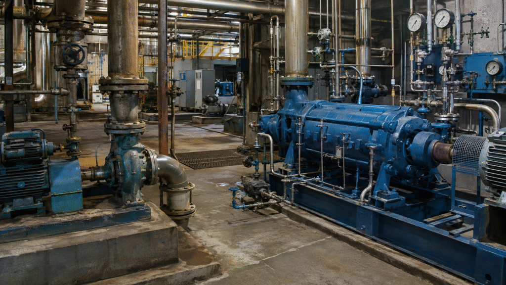
Mechanical Seals for Hot Water and Boiler Feed Pumps
Mechanical seals for hot water and boiler feed pumps operate under demanding conditions. High temperature reduces the liquid margin above its boiling point. Meanwhile, pressure, speed, and rapid temperature changes increase stress on the seal faces.
A seal that performs well in cold water may fail quickly in hot service. The failure may start with vapor formation, damaged elastomers, excessive face loading, poor cooling, or thermal distortion.
Therefore, reliable selection requires more than a temperature rating. Engineers must review the seal design, face materials, elastomers, operating pressure, water chemistry, cooling system, and startup procedure.
Our mechanical seal material selection guide explains how temperature, pressure, fluid properties, and component materials work together. This article focuses on the additional challenges created by hot water and boiler feed applications.
Quick Answer: Which Mechanical Seal Is Best for Hot Water Pumps?
A balanced mechanical seal with carbon against silicon carbide faces is a common starting point for clean hot water. EPDM may suit many water-based applications. However, the exact compound must match the maximum temperature and water-treatment chemicals.
Boiler feed pumps often require a more engineered solution. Possible features include:
- Balanced seal faces
- Stationary seal construction
- Cartridge installation
- High-temperature secondary seals
- Controlled seal-chamber cooling
- An internal pumping ring
- API Plan 23 circulation
- A close-clearance throat bushing
- Materials approved for low-conductivity water
- A design that tolerates high pressure and shaft movement
The pump manufacturer or seal engineer must approve the final specification. Do not select a boiler feed pump seal from shaft size and temperature alone.
Hot Water Pumps vs Boiler Feed Pumps
Hot water and boiler feed pumps both handle heated water. However, their operating demands can differ greatly.
| Operating Factor | Hot Water Circulation Pump | Boiler Feed Pump |
|---|---|---|
| Typical duty | Heating, process circulation, heat transfer | Supplying treated water to a boiler |
| Pressure | Low to high, depending on system | Often high or very high |
| Water quality | May contain minerals, inhibitors, or treatment chemicals | Often treated or demineralized |
| Seal challenge | Heat, cycling, deposits, and vaporization | Heat, pressure, speed, low lubricity, and flashing risk |
| Common seal design | Component or cartridge seal | Engineered cartridge or stationary seal |
| Cooling requirement | Application-dependent | Frequently critical |
| Support system | Plan 11, 21, 23, or another approved arrangement | Plan 23 or another engineered system may be required |
A building-heating pump operating at moderate pressure does not have the same requirements as a power-station boiler feed pump.
Therefore, terms such as “hot water seal” are not precise enough for ordering. Always provide the actual seal-chamber conditions.
Why Mechanical Seals for Hot Water Pumps Fail Early
High temperature changes how water behaves inside the seal chamber.
Vaporization at the Seal Faces
Mechanical seal faces require a thin liquid film for lubrication and cooling. However, friction creates heat at the running interface.
At the same time, pressure can drop as the liquid moves across the seal faces. If the local temperature reaches the boiling point at that pressure, part of the water can turn into vapor.
This process can cause:
- An unstable lubricating film
- Intermittent face contact
- Increased friction
- Rapid temperature changes
- Heat checking
- Carbon blistering
- Face distortion
- Noise and vibration
- Leakage during changing loads
The bulk water inside the pump may remain liquid while vapor forms locally at the sealing interface. Therefore, checking only the pump discharge temperature does not confirm safe seal operation.
Limited Lubricity
Clean and demineralized boiler feed water can provide limited lubrication at the seal faces. The problem becomes more severe as temperature rises.
Excessive face loading can then produce more friction and heat. For this reason, many hot-water seals use a balanced design to reduce the effective hydraulic closing force.
Cooling the seal chamber can also improve the operating environment. However, the cooler, piping, pumping ring, and throat bushing must function as a complete system.
Thermal Expansion and Distortion
The shaft, sleeve, gland, seal faces, pump casing, and fasteners may heat at different rates.
Uneven expansion can change:
- Seal working length
- Gland alignment
- Face flatness
- Shaft position
- Spring compression
- O-ring movement
- Piping loads at the pump
Frequent starts and stops increase this risk. Our guide to thermal assault in mechanical seals explains how rapid temperature changes, dry running, and poor cooling damage sealing components.
Elastomer Hardening or Swelling
Temperature can accelerate elastomer ageing. In addition, oxygen-removal chemicals, corrosion inhibitors, cleaning chemicals, oils, and other contaminants may affect the secondary seals.
An unsuitable O-ring may:
- Harden
- Crack
- Swell
- Soften
- Take a permanent compression set
- Stick to the shaft or sleeve
- Lose its ability to move
- Leak during cooling or startup
Therefore, the elastomer must match the complete water chemistry and temperature cycle.
Deposits and Scale
Not every hot-water system uses demineralized water. Minerals, corrosion products, pipe scale, and treatment chemicals may reach the seal chamber.
Deposits can collect around springs, O-rings, and narrow clearances. They may also restrict the cooler or flush line.
As a result, the seal may lose movement or cooling even though the face materials remain in good condition.
Information Required Before Selecting the Seal
Collect real operating data before choosing materials or requesting a quotation.
Record:
- Pump manufacturer
- Complete pump model
- Pump serial number
- Existing seal code
- Shaft or sleeve diameter
- Seal working length
- Seal-chamber dimensions
- Single or double seal arrangement
- Balanced or unbalanced construction
- Rotating or stationary design
- Normal seal-chamber pressure
- Maximum seal-chamber pressure
- Suction pressure
- Discharge pressure
- Normal water temperature
- Maximum water temperature
- Startup and shutdown temperatures
- Shaft speed
- Start-and-stop frequency
- Water-treatment chemicals
- pH and conductivity
- Dissolved solids
- Suspended particles
- Existing cooling or flush plan
- Cooling-water temperature and availability
- Previous seal life
- Previous failure symptoms
Do not use the motor power or pump model as the only selection information. Pumps within one series may use different shafts, seal chambers, materials, or cooling arrangements.
When the part number is missing, use our mechanical seal identification guide. Clear photographs, dimensions, pump information, and operating data should be reviewed together.
Best Mechanical Seal Face Materials for Hot Water
The face pair must control friction, heat, wear, and corrosion. However, no face combination can correct poor cooling or dry operation.
Carbon Graphite
Carbon graphite commonly runs against a harder stationary face. It offers low friction and good thermal behavior in many water applications.
Possible advantages include:
- Good running characteristics
- Low friction against a hard mating face
- Resistance to moderate thermal shock
- Wide availability
- Multiple grades for different duties
However, carbon grades are not identical. Resin-impregnated and antimony-impregnated carbon can have different temperature, strength, chemical, and blister-resistance properties.
The seal manufacturer should choose the grade for the actual pressure, temperature, speed, and water chemistry.
Silicon Carbide
Silicon carbide offers high hardness, corrosion resistance, and good thermal conductivity. It is a common mating material for carbon in hot-water seals.
Possible benefits include:
- Good heat transfer
- Strong wear resistance
- Good dimensional stability
- Resistance to many water-treatment chemicals
- Suitability for clean and mildly contaminated water
However, reaction-bonded and sintered silicon carbide are different materials. Their chemical behavior and construction should not be treated as identical.
In addition, low-conductivity boiler feed water can create special tribological or electrochemical problems with some face grades. Therefore, use a material combination that has been approved for boiler feed service.
Tungsten Carbide
Tungsten carbide provides strength, wear resistance, and toughness. It may suit selected high-load or mechanically demanding applications.
However, it is not automatically the best choice for every hot-water pump.
The binder material can affect corrosion resistance. Moreover, a hard face still requires a stable lubricating film and adequate cooling.
Select tungsten carbide only after checking:
- Binder grade
- Water chemistry
- Operating pressure
- Shaft speed
- Face loading
- Cooling arrangement
- Previous failure mode
Carbon vs Silicon Carbide
Carbon against silicon carbide is a practical starting combination for many clean hot-water pumps.
The carbon face provides low friction. Meanwhile, the silicon carbide face provides hardness and heat transfer.
Nevertheless, the correct carbon grade matters. The final combination must also resist the maximum pressure, temperature, and chemical treatment.
Silicon Carbide vs Silicon Carbide
Silicon carbide against silicon carbide may be considered when the water contains abrasive particles or corrosion products.
However, hard-on-hard faces can generate problems if lubrication becomes unstable. They may also be less forgiving during dry startup or incorrect installation.
Therefore, do not choose this combination from hardness alone.
Engineered and Coated Face Materials
Critical boiler feed pumps may use engineered face grades, special geometries, or surface coatings. These solutions can address electrical corrosion, distortion, low lubricity, or unstable vapor conditions.
The EagleBurgmann hot boiler water sealing case study shows why an engineered seal, controlled circulation, and thermal management may all be necessary in severe service.
Such designs should be selected as a complete system. Do not copy one coated material into a different seal without engineering approval.
Best Elastomers for Hot Water Pump Mechanical Seals
The secondary seal material must remain flexible throughout startup, normal operation, shutdown, and chemical cleaning.
EPDM
EPDM is often a strong starting point for hot water and many water-based chemicals.
It may suit:
- Heating water
- Treated water
- Dilute acids
- Dilute alkalis
- Some oxidizing chemicals
- Selected steam-related applications
However, compound formulation affects performance. EPDM is also generally unsuitable for petroleum oils, fuels, and many hydrocarbons.
FKM
FKM performs well with many oils, fuels, acids, and higher-temperature chemicals.
However, FKM is not automatically better than EPDM in hot water. Some FKM compounds can perform poorly in steam, hot water, amines, or alkaline conditions.
Therefore, choose FKM only after reviewing the actual fluid and compound data.
FFKM
FFKM provides broad chemical and temperature resistance. It may suit critical applications with complex chemical exposure.
Nevertheless, FFKM is expensive. In addition, different FFKM compounds have different performance limits.
Use it when the operating conditions justify the cost and the seal manufacturer approves the grade.
PTFE-Based Secondary Seals
PTFE offers broad chemical resistance and high-temperature capability. However, it does not behave like a conventional rubber O-ring.
PTFE-based secondary seals may require:
- Special profiles
- Spring energizers
- Controlled surface finishes
- Careful installation
- A seal design that allows limited elasticity
Do not replace an elastomer O-ring with a simple PTFE ring unless the seal was designed for it.
The Parker O-Ring Handbook provides useful general information about elastomer properties. However, the seal supplier must still verify the exact compound and exposure conditions.
Should You Use a Metal Bellows Seal?
A metal bellows seal removes the dynamic elastomer that normally slides along the shaft or sleeve. Therefore, it can reduce problems caused by O-ring sticking, deposits, and high-temperature ageing.
Possible advantages include:
- No dynamic O-ring on the shaft
- Good response to axial movement
- Fewer product deposits around a sliding secondary seal
- Suitability for selected high-temperature duties
- Controlled spring force from the bellows assembly
However, a metal bellows seal is not automatically required for hot water.
The bellows material must resist corrosion and fatigue. The seal may also contain static gaskets or O-rings. Moreover, pressure capability, vibration, installation space, and welding quality remain important.
For ordinary hot-water pumps, a correctly selected balanced pusher seal may provide a simpler solution.
Balanced vs Unbalanced Seals
An unbalanced seal exposes more effective face area to hydraulic pressure. Therefore, pressure creates a higher closing force.
This design can work in general low-pressure water service. However, the increased face loading may generate excessive heat in hot or high-pressure applications.
A balanced seal reduces the effective hydraulic load on the faces. As a result, it can offer:
- Lower friction
- Reduced heat generation
- Improved performance at higher pressure
- Better operation with limited lubricity
- Lower risk of rapid face wear
Nevertheless, the balance ratio must match the seal design and operating range. Technicians cannot confirm it from the outside appearance alone.
Rotating vs Stationary Mechanical Seals
In a rotating seal, the spring-loaded assembly rotates with the shaft. This arrangement is common in general industrial pumps.
In a stationary seal, the spring-loaded section remains stationary while the mating component rotates.
Stationary designs may offer advantages in high-speed or large-shaft applications because they can be less sensitive to shaft deflection and rotating mass.
Therefore, engineered boiler feed pump seals often use stationary construction. However, the pump, gland, shaft, and support system must accommodate the design.
Component vs Cartridge Seals
Component mechanical seals can provide an economical solution for standard hot-water pumps. However, installers must set the correct working length and spring compression.
Cartridge seals arrive as preassembled units. They can reduce installation errors involving:
- Working length
- Face alignment
- Spring setting
- Gland position
- Sleeve location
- Component orientation
For critical boiler feed pumps, cartridge construction can improve installation consistency. It also makes it easier to integrate pumping rings, glands, ports, and throat bushings.
For a relevant product reference, review our H7N/H75 boiler feed pump mechanical seal. Confirm the pump model, shaft size, pressure, temperature, face materials, and elastomers before ordering.
Why the Seal Support System Is Critical
The mechanical seal and support system must operate together. A premium seal can still fail if the flush line, cooler, or circulation device does not work.
The support system may need to:
- Remove heat
- Maintain liquid at the seal faces
- Increase vapor-pressure margin
- Vent trapped air
- Prevent deposits
- Keep hot process water away from the seal chamber
- Maintain circulation during operation
- Control temperature during standby
The correct plan depends on the pump and operating conditions.
API Plan 11
Plan 11 sends fluid from a high-pressure area of the pump through an orifice to the seal chamber.
It is common in clean services. It can also help vent the seal chamber and increase pressure at the seal.
However, it returns hot pump discharge fluid directly to the seal chamber. Therefore, Plan 11 may not provide enough cooling for demanding hot-water service.
API Plan 21
Plan 21 adds a cooler to a discharge recirculation line.
The fluid travels from the pump discharge through an orifice and cooler. It then enters the seal chamber.
Plan 21 can reduce seal-chamber temperature. However, the cooler must handle both seal heat and heat carried by the continuous process flow.
API Plan 23
Plan 23 circulates fluid from the seal chamber through a cooler and back to the seal chamber.
An internal pumping ring normally creates the circulation. In addition, a close-clearance throat bushing helps isolate the cooler seal-chamber fluid from the hotter pump liquid.
This arrangement can:
- Cool a smaller volume of water
- Reduce cooler duty
- Increase vapor-pressure margin
- Improve the face lubrication environment
- Limit the entry of hot process water
- Maintain a more stable seal-chamber temperature
The Flowserve mechanical seal piping plans describe Plan 23 as a standard flush plan for boiler feed water and hot-water service above 80°C.
However, Plan 23 requires correct engineering. Important details include:
- Pumping-ring direction
- Pumping-ring performance
- Pipe diameter
- Pipe length
- Cooler pressure drop
- Cooler capacity
- Throat-bushing clearance
- Gland-port orientation
- Cooling-water supply
- Proper venting
- Standby heat transfer
- Temperature monitoring
The cooler and piping must be vented before startup. Otherwise, trapped air can stop circulation or reduce heat transfer.

API Plan 32
Plan 32 injects clean external fluid into the seal chamber.
It can provide cooling and isolate the seal from contaminated process water. However, the external fluid must be compatible with the boiler system.
In high-purity boiler feed applications, an external flush may change the water chemistry. Therefore, the plant must approve the fluid source and injection rate.
Dual-Seal Support Systems
Some critical applications use dual mechanical seals with a buffer or barrier-fluid system.
This arrangement may provide additional leakage control and face lubrication. However, it also adds equipment, instrumentation, and maintenance requirements.
Do not select a dual seal only because the water is hot. Review pressure, safety, emission control, reliability, and contamination requirements first.
How to Select Mechanical Seals for Hot Water Step by Step
Use a structured selection process.
Step 1: Identify the Existing Seal
Record the complete pump and seal information.
Keep the old rotating assembly, stationary seat, gland, sleeve, gaskets, and setting devices together. Photograph every component before cleaning away markings.
Step 2: Confirm the Real Seal-Chamber Conditions
Do not use pump discharge pressure as an automatic substitute for seal-chamber pressure.
Record normal, minimum, and maximum values. Also review startup, low-flow, standby, and shutdown conditions.
Step 3: Review the Water Chemistry
Identify:
- Demineralized water
- Dissolved oxygen
- Ammonia
- Amines
- Hydrazine alternatives
- Corrosion inhibitors
- Glycol
- Chlorides
- Cleaning chemicals
- Suspended corrosion products
- Oil contamination
The same seal materials may behave differently when the treatment programme changes.
Step 4: Calculate the Thermal Risk
Compare seal-chamber pressure with the water vapor pressure at the expected face temperature.
Also consider frictional heat, heat transfer from the pump, cooler performance, and process changes.
A seal engineer should perform the final thermal calculation for critical equipment.
Step 5: Select the Seal Design
Confirm whether the application requires:
- Balanced or unbalanced construction
- Rotating or stationary design
- Component or cartridge installation
- Single or double arrangement
- Pusher or metal bellows construction
- An internal pumping ring
- A special high-pressure face design
Step 6: Select the Face Pair
Match the materials to pressure, temperature, speed, water chemistry, lubrication, and contamination.
Do not approve a material only because it has a high maximum temperature in a general catalogue.
Step 7: Select the Secondary Seals
Check the normal temperature, maximum temperature, chemical-treatment cycle, and shutdown conditions.
Confirm the exact compound rather than relying on the general labels EPDM, FKM, or FFKM.
Step 8: Select the Metal Components
Review corrosion, fatigue, pressure, and thermal expansion.
Possible materials include:
- 316 stainless steel
- Duplex stainless steel
- High-strength stainless steel
- Nickel-based alloys
- Application-specific spring alloys
The correct choice depends on water chemistry and mechanical loading.
Step 9: Confirm the Support Plan
Review the entire piping arrangement.
For Plan 23, confirm the pumping ring, throat bushing, cooler, pipe routing, vents, instruments, and cooling-water supply.
Step 10: Review the Previous Failure
The old seal can reveal the real operating problem.
Do not discard it before completing the investigation.
Common Failure Evidence and Possible Causes
| Failure Evidence | Possible Cause |
|---|---|
| Heat checking on a hard face | Vaporization, thermal cycling, or poor cooling |
| Carbon blistering | Pressure cycling, absorbed liquid, or unsuitable carbon grade |
| Polished dry-looking faces | Insufficient liquid film or dry operation |
| Heavy carbon wear | Excessive face loading, poor lubricity, or misalignment |
| Cracked stationary face | Thermal shock, impact, or distorted installation |
| Uneven wear track | Shaft movement, gland misalignment, or face distortion |
| Hardened O-ring | Excessive temperature or chemical ageing |
| Swollen O-ring | Chemical incompatibility |
| O-ring stuck to the sleeve | Deposits, heat, or unsuitable material |
| Corroded springs | Incompatible metal or water chemistry |
| Scale inside the seal chamber | Mineral deposits or treatment-chemical residue |
| Hot cooler outlet with little temperature difference | Low cooling-water flow or cooler fouling |
| Unstable temperature | Poor circulation, vapor pockets, or changing process conditions |
| Leakage after shutdown | Thermal distortion, pressure change, or secondary-seal damage |
| Leakage only during startup | Dry faces, trapped air, incorrect venting, or rapid heating |

Inspect the bearings, shaft, sleeve, impeller, coupling, and piping loads as well. Replacing the seal alone will not correct pump vibration or shaft movement.
Installation Requirements for Hot-Water Seals
Correct materials can still fail after poor installation.
Follow the pump and seal manufacturers’ instructions. In addition, use our mechanical seal installation guide to review cleaning, face handling, working length, gland alignment, and startup checks.
Important installation practices include:
- Lock out and isolate the pump
- Allow the equipment to cool safely
- Release all internal pressure
- Clean the seal chamber
- Inspect the shaft and sleeve
- Check shaft runout and end play
- Replace damaged gaskets
- Use compatible assembly lubricant
- Keep lapped faces clean
- Do not touch faces with bare hands
- Install the stationary seat evenly
- Set the correct working length
- Tighten gland bolts evenly
- Connect all cooling and flush lines correctly
- Check the pumping-ring rotation
- Vent the cooler and seal chamber
- Remove cartridge setting clips at the correct stage
Do not hammer the seal onto the shaft. Also, do not reuse heat-damaged O-rings because they still look undamaged.
Startup and Shutdown Procedure
Hot-water seals require controlled commissioning.
Before startup:
- Fill and vent the pump.
- Fill the seal chamber with liquid.
- Open the cooling-water supply.
- Open the required flush or circulation valves.
- Vent the cooler and high points.
- Confirm the correct valve positions.
- Check the direction of rotation.
- Confirm that the pump is not running dry.
- Verify that temperature instruments work.
- Check for external leakage.
During startup, warm the pump according to the manufacturer’s procedure. Avoid rapid temperature changes when possible.
Monitor:
- Seal leakage
- Seal-chamber temperature
- Cooler inlet temperature
- Cooler outlet temperature
- Cooling-water flow
- Pump vibration
- Bearing temperature
- Pump pressure
- Unusual noise
During shutdown, follow the specified cooling procedure. Some systems must maintain cooling or circulation while the pump remains hot.
A sudden loss of flow can create temperature layering, vapor pockets, or seal distortion. Therefore, standby conditions deserve the same attention as normal operation.
Maintenance Checklist
During routine inspections, check:
- Visible leakage
- Deposits around the gland
- Seal-chamber temperature
- Cooler inlet and outlet temperatures
- Cooling-water flow
- Flush-line temperature
- Vibration
- Bearing condition
- Pressure changes
- Valve positions
- Blocked vents
- Cooler fouling
- Pipe corrosion
- Loose connections
- Abnormal startup behavior
Record the values instead of writing only “normal.”
A gradual increase in temperature may reveal reduced circulation before visible leakage begins.
If leakage starts after replacement, use our mechanical seal leaking after installation guide to check working length, face cleanliness, elastomer damage, gland alignment, dry running, and pump condition.
Common Selection Mistakes
Selecting by Maximum Temperature Alone
A published temperature limit does not confirm suitability.
Pressure, speed, water chemistry, face loading, cooling, and thermal cycling also affect seal life.
Using FKM for Every High-Temperature Application
FKM has strong heat resistance in many fluids. However, it may not be the best choice for hot water, steam, amines, or alkaline conditions.
Choosing the Hardest Face Pair
Hardness cannot prevent vaporization or dry running. The seal still needs lubrication and heat removal.
Ignoring Low-Conductivity Water
Boiler feed water can create different face conditions from ordinary tap water. Use face grades approved for the service.
Installing Plan 23 Without Checking Circulation
A cooler alone does not guarantee cooling.
Poor pipe routing, trapped air, an incorrect pumping ring, or excessive pressure drop can stop effective circulation.
Ignoring Standby Conditions
A pump may operate reliably but leak after shutdown. Heat soak and temperature layering can distort seal and pump components.
Copying Another Pump’s Seal Specification
Two boiler feed pumps may have different pressures, speeds, shaft sizes, seal chambers, or water-treatment programmes.
Confirm each pump separately.
Hot Water and Boiler Feed Pump Seal Checklist
Before ordering, confirm:
- Complete pump model
- Serial number
- Existing seal code
- Shaft or sleeve diameter
- Seal working length
- Gland and chamber dimensions
- Normal and maximum pressure
- Normal and maximum temperature
- Shaft speed
- Water chemistry
- Conductivity
- Treatment chemicals
- Solids and corrosion products
- Face material grades
- Elastomer compound
- Metal component materials
- Balanced or unbalanced design
- Rotating or stationary construction
- Single or double arrangement
- Component or cartridge construction
- Existing piping plan
- Cooler capacity
- Cooling-water conditions
- Pumping-ring design
- Throat-bushing clearance
- Startup and shutdown procedure
- Previous seal life
- Previous failure evidence
Frequently Asked Questions
Can a Standard Water Pump Seal Handle Hot Water?
Sometimes. It depends on the temperature, pressure, speed, materials, and cooling arrangement.
Do not assume that a seal rated for cold water can operate reliably in hot water.
Which Face Combination Is Best for Hot Water?
Carbon against silicon carbide is a common starting point for clean hot water. However, the carbon grade and silicon carbide grade must suit the operating conditions.
Is EPDM Better Than FKM for Hot Water?
EPDM often performs well in water-based service. FKM may suit oils and many chemicals, but it is not universally better for hot water.
Always check the exact compound and water chemistry.
Why Does a Hot-Water Seal Leak Only During Startup?
Possible causes include trapped air, dry faces, rapid heating, thermal distortion, incorrect working length, or delayed cooling flow.
Why Does the Seal Leak After Shutdown?
Heat soak, pressure changes, temperature layering, and secondary-seal shrinkage can cause shutdown leakage.
Does Every Boiler Feed Pump Need API Plan 23?
No. However, Plan 23 is widely used for hot, clean water because it cools the seal-chamber fluid efficiently.
The final piping plan must match the pump, seal, temperature, pressure, and plant requirements.
Can Silicon Carbide Run Dry?
Do not assume it can. Silicon carbide still generates heat without an adequate liquid film.
Only use dry-running capability when the complete seal design specifically allows it.
Is a Metal Bellows Seal Required for Boiler Feed Water?
Not always. Some applications use balanced pusher or stationary cartridge seals successfully.
Metal bellows may help when dynamic elastomers, deposits, or temperature limits create problems.
What Information Should I Send to a Seal Supplier?
Send the pump nameplate, seal code, clear photographs, critical dimensions, face materials, water chemistry, pressure, temperature, speed, piping plan, and failure history.
Final Recommendations
Mechanical seals for hot water pumps need stable lubrication, correct face loading, compatible materials, and controlled heat removal.
For moderate clean-water service, a balanced carbon against silicon carbide seal with a suitable EPDM compound may provide a practical starting point.
However, boiler feed pumps can require stationary cartridge seals, engineered face grades, high-pressure construction, and a properly designed Plan 23 cooling system.
Do not treat the cooler as an optional accessory. Likewise, do not select the seal from temperature alone.
Review the pump, seal, water chemistry, operating cycle, and support system as one complete unit. This approach reduces vaporization, thermal damage, repeated leakage, and unexpected downtime.