The mechanical seal working principle begins with a simple problem: a rotating shaft must pass through a stationary pump casing without uncontrolled process leakage. A mechanical seal controls that path with precision faces, secondary seals, flexible loading parts, and a drive system. Reliable operation depends on balancing sealing, lubrication, heat removal, and face loading.
In a typical wet-running pump seal, one face rotates with the shaft while the other stays stationary with the housing. The faces run extremely close together, while a thin fluid film supports lubrication and heat control. Meanwhile, secondary seals close other leakage paths around the shaft, sleeve, gland, and seal components.
Where Does a Pump Mechanical Seal Actually Stop Leakage?
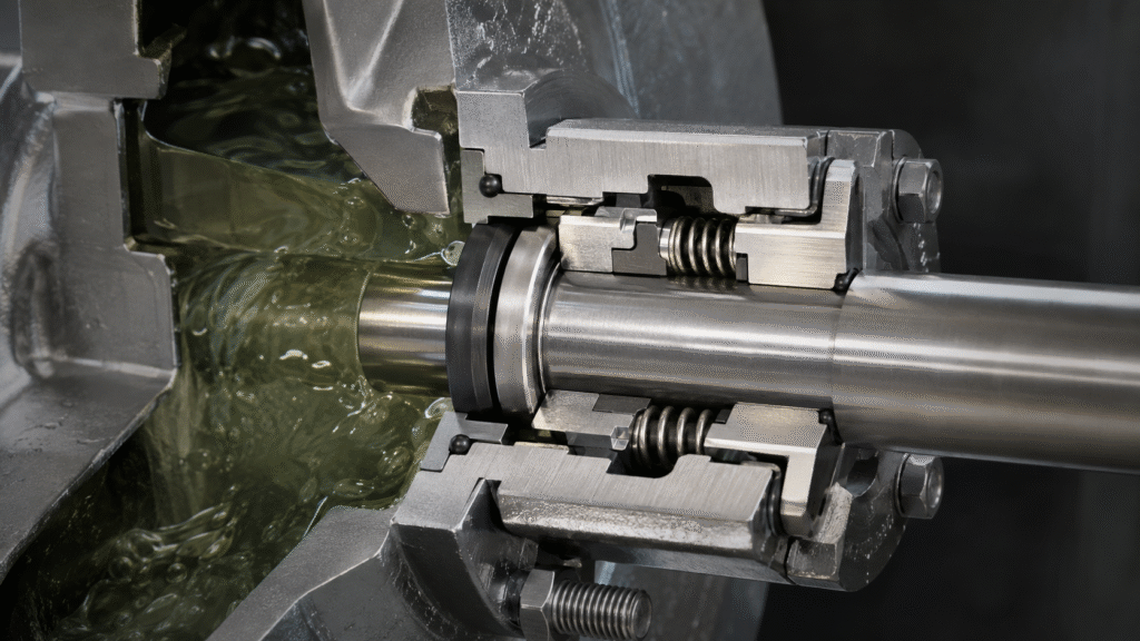
A pump shaft creates a leakage path where it exits the pressurized casing. The seal controls this path through a primary dynamic interface and secondary sealing points. The primary interface lies between the rotating and stationary faces, where pressure tends to drive fluid outward.
However, the faces maintain a controlled contact or very small separation during operation. Therefore, flow across the interface remains restricted while the shaft keeps rotating. Secondary seals then prevent fluid from bypassing the faces through gaps around the shaft, sleeve, stationary seat, housing, or gland.
The Two Primary Seal Faces
The two primary faces form the core of mechanical seal operation. Manufacturers lap these surfaces very flat because uneven contact creates local openings and unstable loading. However, the goal is not to force two dry surfaces together as tightly as possible.
Rotating Seal Face
First, the rotating face follows the shaft or sleeve. Set screws, collars, pins, spring-driven features, or bellows may transmit torque, depending on the design. At the same time, the movable assembly usually needs limited axial freedom so the face can maintain its working relationship as wear or small shaft movements occur.
Stationary Seal Face
Meanwhile, the stationary face remains fixed relative to the pump housing or gland and provides the mating surface. An O-ring, cup, gasket, or similar element seals around the seat, preventing fluid from escaping around it instead of crossing the primary interface.
How the Mechanical Seal Working Principle Creates a Seal
A mechanical seal needs closing forces to maintain the intended face relationship. At the same time, opening forces act within the fluid film. Therefore, stable operation occurs when those forces create suitable face loading for the specific geometry and service conditions.
Initial Face Contact
Before normal pump pressure develops, the seal still needs enough force to establish the face interface. Springs or bellows provide this initial preload during assembly, startup, shutdown, and low-pressure operation. However, more compression is not automatically better because excessive loading increases friction and heat.
Spring or Bellows Preload
Springs and bellows do more than press the faces together. They compensate for face wear and limited axial movement while helping the movable face track its mate. Designs may use single springs, multiple springs, rubber bellows, or metal bellows, but each provides controlled preload and movement.
Hydraulic Forces
Process pressure also acts on the seal faces. Its effect depends on effective pressure area, geometry, pressure direction, and fluid distribution. Meanwhile, the fluid film produces an opening force that opposes part of the closing load. Balanced and unbalanced designs change how pressure affects that load. However, this is only one part of the mechanical seal working principle. A balanced vs unbalanced mechanical seals guide is better for detailed design comparison.
Why a Thin Fluid Film Is Essential
Next, the fluid film explains much of how mechanical seals work. In a normal wet-running contact seal, process fluid or a suitable support fluid enters the microscopic interface between the lapped faces. Its thickness is not universal because pressure, speed, viscosity, temperature, geometry, and surface condition all influence the film.
Lubrication Between Seal Faces

The film reduces severe direct rubbing between microscopic surface high points. Therefore, it lowers friction and controls wear while the shaft rotates. Some microscopic contact may still occur in contacting liquid seals, but the intended operating condition is a controlled lubrication regime rather than continuous dry friction.
Heat Removal and Friction Control
Face friction creates heat, while fluid shear inside the thin film adds more. In addition, pressure, speed, seal diameter, and face loading affect heat generation. As a result, the surrounding liquid and circulation paths remove that heat. Therefore, cooling, flushing, or circulation can become important when the process fluid cannot maintain a stable interface. An API 682 seal flush plans guide explains common support arrangements.
What Happens if the Film Becomes Unstable?
If the film becomes too thin or disappears, lubrication falls and temperature can rise quickly. As a result, faces may distort, crack, or wear rapidly, while nearby elastomers can suffer heat damage. However, excessive face separation creates the opposite problem because leakage can increase. Consequently, the mechanical seal working principle depends on a narrow balance between leakage control, lubrication, heat removal, and face loading.
How Secondary Seals Stop Bypass Leakage
Primary faces cannot control fluid that travels around them. Therefore, O-rings, rubber bellows, gaskets, wedges, cups, or other secondary elements close bypass paths between seal rings, shafts, sleeves, housings, and glands. In addition, they must remain compatible with the motion required by the seal design.
However, not every secondary seal is fully static. In many pusher seals, an O-ring slides slightly as the movable face adjusts axially. Other O-rings and gaskets remain stationary. Rubber bellows may also flex while sealing, so deposits, swelling, friction, or surface damage can restrict face tracking.
How the Rotating Assembly Is Driven
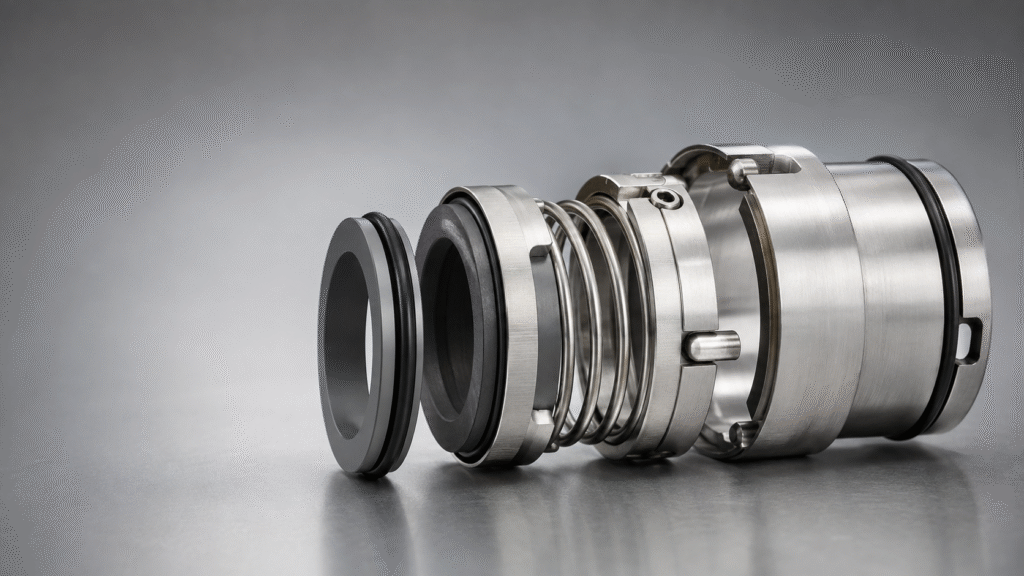
The rotating assembly must follow the shaft reliably. Therefore, mechanical seals use drive elements such as set screws, collars, pins, tabs, spring-driven features, or bellows that transmit torque through their construction. However, no single drive method applies to every seal. The drive must transmit rotation without preventing the limited axial movement required by the flexible sealing element.
How Mechanical Seals Compensate for Wear and Shaft Movement
Seal faces experience gradual wear during service. Therefore, springs or bellows allow the movable assembly to shift axially and preserve the primary interface. This flexibility can also accommodate limited shaft movement within the seal design. However, it cannot correct a bent shaft, worn bearing, excessive runout, or poor alignment. A shaft runout and misalignment guide explains how excessive machine motion disturbs face tracking and fluid-film stability.
Why Mechanical Seal Faces Generate Heat
Face friction and viscous shear inside the fluid film generate heat during normal operation. Higher speed increases sliding velocity, while seal diameter affects surface speed. In addition, pressure and face loading can increase friction when they press the faces together more strongly. Therefore, heat generation changes with both seal geometry and operating conditions.
In addition, suitable materials help manage thermal and wear conditions, but materials cannot replace lubrication. A mechanical seal materials guide explains carbon, ceramic, silicon carbide, and tungsten carbide separately. In demanding service, correct circulation or cooling may also be necessary to maintain stable mechanical seal operation.
Does a Mechanical Seal Allow Leakage?
In practice, a mechanical seal controls process leakage; it does not depend on an absolute promise of zero leakage. In wet-running contact seals, the primary interface contains a very thin fluid film. Some fluid can move through that interface, and part may evaporate or appear only as slight moisture.
The acceptable level depends on seal design, fluid, application risk, environmental requirements, and industry rules. Therefore, one leakage number cannot describe every seal or service condition. A single vs double mechanical seals guide explains how different arrangements manage process leakage.
How Different Seal Designs Use the Same Basic Principle
Component, cartridge, single, double, rubber bellows, and metal bellows seals can look very different. However, most wet-running pump designs still depend on a controlled primary face interface, reliable secondary sealing points, suitable face loading, and stable lubrication between the faces.
For example, cartridge construction packages components into a preassembled unit, while component seals use separate parts. Double seals add another sealing interface, and bellows designs change the flexible sealing arrangement. These differences affect installation and application, but they do not replace the basic sealing principle. Therefore, use a mechanical seal selection guide for application decisions rather than turning a working-principle explanation into a selection rule.
What Causes the Mechanical Seal Working Principle to Break Down?
The sealing mechanism becomes unstable when the faces lose the conditions they need. For example, dry running removes lubrication, while incorrect loading can create excess heat or separation. Contamination can damage faces or restrict moving secondary seals. In addition, runout, misalignment, vibration, and cavitation disturb the face relationship. Wrong materials may swell, corrode, crack, or wear. Therefore, leakage can originate from the seal, the pump, or the operating system.
For lubrication loss, the guide on what happens when a mechanical seal runs dry explains the damage sequence in detail. Meanwhile, broader diagnosis belongs in the site’s mechanical seal failure guide. This keeps the mechanical seal working principle focused on how sealing operates rather than turning it into a troubleshooting manual.
Mechanical Seal Working Principle FAQ
What is a mechanical seal?
A mechanical seal controls process leakage where a rotating shaft passes through a stationary equipment housing. Precision faces create the primary sealing interface, while secondary elements stop fluid from bypassing those faces through other paths. Therefore, the seal can contain fluid while still allowing continuous shaft rotation.
Which part rotates?
One primary face rotates with the shaft or sleeve through the drive mechanism. Depending on the construction, other rotating parts may include springs, collars, retainers, bellows, or secondary sealing elements. However, the exact rotating assembly varies between component, cartridge, pusher, and bellows designs.
Which part stays stationary?
The mating face or stationary seat remains fixed relative to the housing or gland. A secondary seal normally closes the leakage path around that stationary component. Therefore, fluid should cross only the controlled primary interface rather than escape around the outside of the stationary seat.
Why is a fluid film needed?
The film lubricates the primary faces, helps remove heat, and controls friction and wear. In addition, it supports relative motion between two extremely flat surfaces. Therefore, stable film behavior is central to the mechanical seal working principle in normal wet-running service.
Why do mechanical seal faces need lubrication?
Without adequate lubrication, direct face contact becomes more severe. As a result, friction rises, heat increases, and the faces can distort or wear rapidly. The liquid film provides the controlled interface needed for normal wet-running operation while helping the seal manage heat at the sliding surfaces.
Do mechanical seals allow any leakage?
Yes. Controlled leakage can exist across the face interface in wet-running seals. However, its amount and appearance depend on design, fluid, pressure, temperature, application, and containment requirements. Therefore, one universal leakage value should not be applied to every mechanical seal or pumping service.
What happens when the fluid film disappears?
The interface moves toward dry running when the liquid film disappears. Consequently, friction and temperature rise, while distortion, cracking, rapid wear, and elastomer damage can follow. Severity depends on seal design, materials, speed, face loading, and the duration of lubrication loss.
What is the purpose of the spring?
The spring provides initial closing preload and compensates for face wear and limited axial movement. In addition, it helps the movable face track its mate during operation. However, it should not force the faces together more tightly than the design requires.
What do O-rings and other secondary seals do?
They stop process fluid from bypassing the primary faces around the shaft, sleeve, seat, gland, or other components. Some remain static, while others move slightly during operation. Therefore, secondary elements must seal their local leakage path while allowing movement required by the design.
The mechanical seal working principle is a controlled interaction rather than simple clamping. Flat faces restrict leakage, a thin fluid film manages lubrication and heat, flexible elements maintain face loading, and secondary seals close bypass paths. Together, these functions let the shaft rotate while the sealing system controls process fluid.