Mechanical seal installation is not finished when the new seal fits onto the shaft. Reliable results depend on clean handling, accurate axial setting, prepared support systems, and controlled startup. Therefore, technicians should treat installation as one sequence from pump inspection through commissioning and routine observation.
This guide follows that sequence for pump mechanical seals. It also separates component seals from cartridge seals because their positioning methods are different. Therefore, use the pump drawing, seal drawing, and manufacturer instructions when they specify dimensions, tolerances, tightening values, or sequence.
Before You Install a Mechanical Seal
Good mechanical seal installation begins before the package is opened. First, isolate the pump, relieve pressure, drain or contain the process liquid, and follow the site’s lockout procedure. Next, confirm that the replacement seal matches the pump and service.
Confirm the Correct Seal
First, check the seal model, shaft or sleeve diameter, stationary seat, working length, direction of rotation where relevant, face materials, elastomers, and required support system. If these details are uncertain, use a mechanical seal selection guide before assembly. A seal that slides onto the shaft is not automatically the correct replacement.
Also compare the new stationary seat with the old seat and pump housing. Differences in seat thickness or mounting style can change axial position. For component seals, the specified working length is especially important because it establishes intended spring compression and face loading.
Inspect the Pump and Shaft
Next, inspect the shaft or sleeve for corrosion, burrs, sharp shoulders, keyways, threads, wear grooves, and other damage. In addition, check bearing condition, shaft movement, runout, and alignment when required. However, do not apply one universal tolerance to every pump. Use the pump manufacturer, seal manufacturer, or equipment specification.
A new seal cannot correct worn bearings, a bent shaft, or serious misalignment. Therefore, correct machine problems before installation. A shaft runout and misalignment guide can help when repeated leakage suggests an equipment problem.
Prepare a Clean Work Area
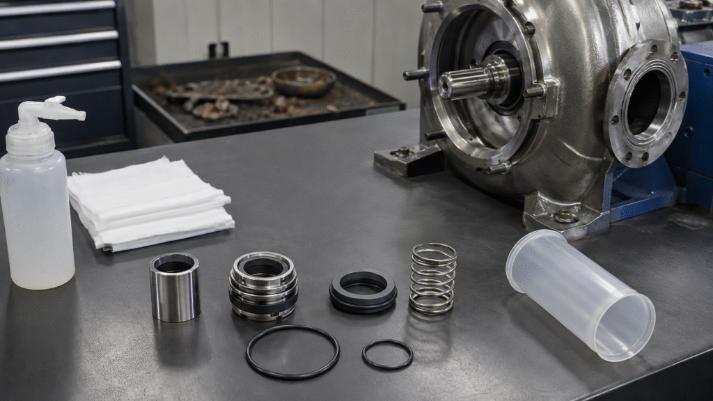
Mechanical seal faces are precision-lapped surfaces. Dust, fibers, metal chips, fingerprints, old gasket material, and dried chemical deposits can hold the faces apart or scratch the sealing track. Therefore, keep new parts covered until needed and use a clean work surface.
Do not place lapped faces on a dirty bench. Likewise, keep rusty hardware, used gaskets, and contaminated tools away from the new seal. Clean working practices protect the primary sealing interface.
Prepare the Shaft, Sleeve and Seal Chamber
First, remove old gasket material, rust, and deposits without damaging locating surfaces. Next, smooth burrs and protect threads or keyways that could cut a secondary seal. Next, clean the shaft, sleeve, seal chamber, gland face, and stationary-seat bore with a residue-free method.
Then, check locating shoulders and bores before assembly. If corrosion or wear has changed a mounting surface, correct the equipment condition first. Do not force a seal over a damaged sleeve or use the seal itself to push past an obstruction.
Handle Seal Faces and Elastomers Correctly
Correct handling prevents many mechanical seal installation problems before they begin. Face materials can be brittle, while elastomers can be cut, twisted, swollen, or contaminated. Therefore, handle each component according to its function rather than ordinary pump hardware.
Protect the Lapped Faces
First, avoid touching lapped seal faces with bare fingers. In addition, do not use sandpaper, dirty cloths, or casual abrasive cleaning. Instead, follow the manufacturer’s cleaning method and use clean, residue-free materials. In addition, protect carbon, ceramic, silicon carbide, and tungsten carbide parts from impact or uneven force.
However, do not automatically grease the primary faces. Some procedures may specify clean wetting, while others require clean handling before startup. Therefore, follow seal-specific instructions instead of applying one universal rule.
Install O-Rings Without Damage
First, confirm that each O-ring or secondary seal has the correct material and size. Next, protect it from threads, keyways, burrs, and sharp shoulders. During assembly, prevent rolling, twisting, pinching, or cutting because hidden elastomer damage can cause immediate leakage.
Therefore, use assembly lubricant only where the manufacturer permits it. The lubricant must also suit the elastomer and process. Never assume every O-ring should receive grease. A mechanical seal materials guide can provide deeper compatibility guidance when materials are uncertain.
Install the Stationary Seat
First, clean the seat bore and confirm that the mounting surface is free from residue or raised damage. Then install the stationary seat squarely with an appropriate tool that loads the correct surface. Do not hammer directly on the precision face or load one side heavily.
Next, check that any rubber cup, O-ring, gasket, or secondary element has not rolled, cut, or extruded. An angled seat should be removed and corrected rather than pulled into position by later gland tightening.
Installing a Component Mechanical Seal
A component seal uses separately installed rotating and stationary parts. Unlike a cartridge, it does not follow one universal setting-clip method. Therefore, the seal drawing, pump specification, locating shoulder, or specified working length must establish the installed position.
Confirm Working Length
Working length determines the rotating element’s axial position and resulting spring compression. Too much compression can increase face load, friction, heat, wear, or even cause spring coil binding. Too little compression can reduce closing force and permit unstable face contact or leakage.
Therefore, do not estimate the setting by appearance or by “tightening the spring.” Position the seal as the design requires. Mechanical seal installation should reproduce intended geometry, not create extra preload in the hope of improving sealing.
Set the Rotating Assembly
Position the rotating component carefully on the prepared shaft or sleeve. Protect elastomers as the part passes shoulders, threads, and keyways. Next, locate the assembly from the correct shoulder, reference dimension, or drawing and secure its drive feature for that seal design.
However, single springs, multiple springs, rubber bellows, collars, and set-screw designs transfer drive differently. Therefore, do not assume every rotating element uses the same retention method.
Install and Tighten the Gland
First, place the gland gasket or static sealing element correctly, then bring the gland squarely against the seal chamber. Next, start fasteners evenly and tighten them progressively in a cross pattern. Use the torque and sequence specified by the pump or seal manufacturer rather than copying another pump.
Uneven tightening can tilt the gland or stationary face and change face loading. Therefore, confirm that the gland seats uniformly around its circumference.
Installing a Cartridge Mechanical Seal
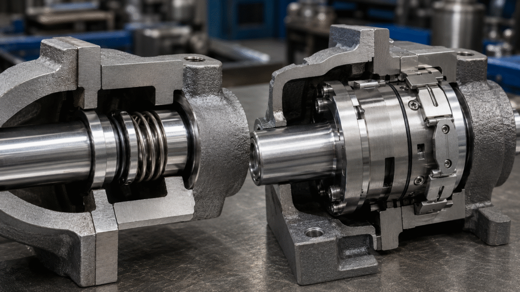
A cartridge seal usually arrives preassembled with its internal face relationship factory set. Setting clips, plates, or spacers may hold that relationship during installation. Therefore, keep those devices as required by the cartridge instructions while fitting the unit to the shaft and gland.
Next, secure the gland, establish the final rotor position, and lock the drive collar in the manufacturer’s sequence. Remove or release setting devices only at the stage specified for that seal. Then confirm free rotation where the equipment procedure permits it. For detailed steps, use the cartridge seal installation guide rather than applying component-seal setting methods.
Connect Flush, Cooling or Barrier Systems
Mechanical seal installation is not complete when the gland is tight. Connect required flush, cooling, quench, vent, drain, buffer, or barrier piping according to the arrangement. Check flow direction, valves, support-fluid availability, venting, and pressure requirements where applicable.mechanical seal support systems
However, do not copy piping from a nearby pump without verification. Different services may need different support conditions. The API 682 seal flush plans guide explains common process-side arrangements, while the approved piping drawing controls installation.
Mechanical Seal Pre-Startup Checklist
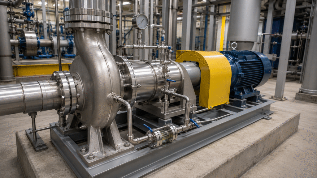
Before energizing the pump, confirm:
- Pump and seal are assembled according to their drawings.
- Shaft rotates freely where manual rotation is permitted.
- Pump and seal chamber contain the required liquid.
- Trapped air has been vented.
- Required flush, cooling, quench, buffer, or barrier systems are operating.
- Valves are in the correct startup positions.
- Rotation direction has been confirmed by an approved method.
- Cartridge setting devices have been handled according to instructions.
- No binding, scraping, loose hardware, or piping strain is obvious.
These checks protect the seal during the transition from assembly to operation.
Commissioning and First Startup
Start the support system in the required sequence before the main pump where specified. Fill and vent the pump and seal chamber so liquid-lubricated faces do not begin operation dry. Loss of the fluid film raises friction and temperature quickly. The guide on what happens when a mechanical seal runs dry explains that mechanism in detail.
Next, during startup, observe leakage, seal-area temperature, vibration, abnormal noise, support-system condition, and pump pressure or flow behavior. Do not invent a universal observation period or acceptable drip rate. If visible leakage continues, temperature rises rapidly, or vibration becomes abnormal, follow the manufacturer or site procedure and investigate rather than assuming the seal needs days to “wear in.”
Mechanical Seal Maintenance During Operation
Routine maintenance should focus on changes. Look for visible leakage, deposits, unusual heat, vibration, noise, blocked support lines, dirty filters where fitted, and changes in process conditions. Also review bearing and alignment condition when operating behavior changes.
In addition, keep records of leakage patterns, temperature trends, support-system condition, and recent process changes. If a problem appears after mechanical seal installation, the guide on mechanical seal leaking after installation can help separate setting errors from pump or operating problems. Repeated adjustment without diagnosis can destroy useful evidence.
What to Inspect During Pump Overhaul
Do not throw the old seal away immediately. Inspect the face wear track, scoring, chipping, thermal cracking, deposits, elastomer swelling or hardening, spring corrosion, sleeve wear, and stationary-seat damage. Photograph unusual patterns before cleaning the parts.
A damaged seal can provide failure evidence. Uneven wear may suggest motion or alignment problems, while deposits may indicate contamination or poor circulation. Therefore, preserve evidence before fitting the next seal.
Common Mechanical Seal Installation Mistakes
Common errors include installing the wrong seal, contaminating or touching the faces, cutting an O-ring, using incompatible lubricant, and setting the wrong working length. Other mistakes include installing the stationary seat crooked, tightening the gland unevenly, or adding excessive component-seal spring compression.
Cartridge errors differ. Removing setting clips at the wrong stage can disturb the preset relationship. In addition, technicians may forget support piping, leave trapped air, start dry, or ignore worn bearings and shaft runout. Correct mechanical seal installation depends on controlling the complete sequence.
Mechanical Seal Installation FAQ
Can I install a component seal using cartridge setting clips?
No general rule allows that. Component seals normally require the working length or axial position specified by their drawing or pump design. Cartridge setting devices belong to cartridge assemblies designed to use them.
Should I lubricate every O-ring before installation?
No. Use only a lubricant and application method approved for the elastomer, process, and seal design. Some positions require lubrication, while unsuitable lubricant or excessive quantity can damage elastomers or contaminate faces.
How tight should gland bolts be?
Use the pump or seal manufacturer’s torque requirement and sequence. There is no reliable universal torque for every gland, fastener, gasket, material, and pump construction. However, progressive and even tightening helps keep the gland square.
Can I start the pump briefly to check rotation?
Only use a rotation-check method that the equipment and seal instructions permit. A liquid-lubricated seal should not face an avoidable dry startup. Confirm priming, venting, support systems, and rotation safely before normal operation.
Does a new mechanical seal need to leak while it runs in?
Do not assume continuous visible leakage is a required break-in condition. Leakage behavior depends on the seal and service. If leakage is persistent, increasing, or accompanied by heat or vibration, follow the applicable procedure and inspect the cause.
Mechanical seal installation succeeds when the correct seal is fitted to a mechanically sound pump under clean, controlled conditions. Set component seals by their required working length, install cartridge seals by their specified setting-device sequence, prepare every support system, and protect faces from dry running. Finally, monitor the pump and preserve evidence during maintenance so installation quality can be separated from machine or process problems.